
Data Sheet


Power jumpers
The setup described above involves three separate power supplies. For some applications, this setup
can be simplified by bridging one or both of the power jumpers on the bottom of the board.
Here are some alternative options for powering your system with fewer than three power supplies:
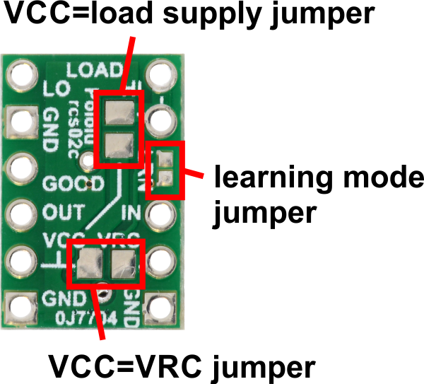
• If the VRC supply from the RC receiver is between 2.5 V and 5.5 V, then you could bridge the
VCC=VRC jumper in order to power the board from VRC and avoid the need for a separate
logic power supply connected to VCC. Alternatively, supplying power to VCC and bridging
VCC=VRC could allow you to power your RC receiver from the RC switch.
• If your load supply is between 2.5 V and 5.5 V, then you could bridge the VCC=load supply
jumper, allowing you to power the board from either the LOAD HIGH or VCC pin.
• With both jumpers bridged, the whole system can be powered from a single suitable source.
Large or capacitive loads can cause problems if the same supply is used for the logic (VCC)
and the load. In such a configuration, when the MOSFET turns on, VCC might drop below
2.5 V, causing the board to reset. If you try to activate the switch but the board just goes
into safe-start mode instead, you might have a power issue, especially if the problem only
happens when the load is connected. If you have this problem, you should consider using
a separate logic power supply, adding a capacitor between GND and VCC, or using shorter
power leads.
Pololu RC Switch User’s Guide © 2001–2017 Pololu Corporation
3. RC Switch with Small Low-Side MOSFET Page 16 of 45