
Data Sheet


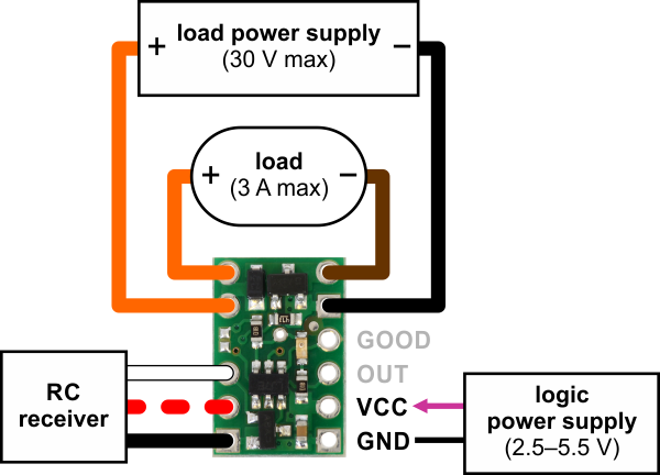
Pololu RC Switch with Small Low-Side MOSFET, typical wiring diagram.
The RC switch can be plugged directly into an RC receiver or servo controller using a Female-
Female servo extension cable. These can be found in our Servo Cables [https://www.pololu.com/category/
112/servo-cables] category. The switch will read the signal from the RC receiver, but in the default
configuration it will not draw or supply any power to the receiver, so the power wire is optional. The
receiver will need its own power source.
Power for the board’s logic needs to be applied to GND and VCC and must be between 2.5 V and
5.5 V. A 5 V regulator would be a good choice for the logic power supply. A 3-cell NiMH battery pack
[https://www.pololu.com/category/104/3.6-v-nimh-battery-packs] would also work, but a 4-cell NiMH battery
pack can be well over 5.5 V when fully charged and would not be suitable.
The negative side of your load supply should connect to the GND pad on the top-right side of the
board, and the negative side of the load itself should connect to the LOAD LOW pin. The two pins
labeled LOAD HIGH are internally connected and will typically be connected to both the load and the
load power supply. There is a flyback (also known as a “freewheeling”) diode between the MOSFET
output and LOAD HIGH, which allows you to safely connect an inductive load such as a motor or
relay. Alternatively, the positive side of the load could be directly connected to the load supply off of
the board. The board’s MOSFET can deliver up to 3 A with VCC at 5 V and can handle load supply
voltages up to 30 V.
Pololu RC Switch User’s Guide © 2001–2017 Pololu Corporation
3. RC Switch with Small Low-Side MOSFET Page 15 of 45