
Data Sheet


This board involves three potentially-different power supplies:
• VCC: The VCC pin powers the basic functions of the
board and needs to be connected to a power source
between 2.5 V and 5.5 V. VCC is also the gate voltage
that is used to turn the MOSFET on, so it should be noted
that lower VCC voltages will lead to higher MOSFET on
resistances, which in turn limits the maximum current the
device can switch.
• VRC: The VRC pin will generally be connected the power line from your RC system. By
default, power from this pin is not used by the board, so this pin is optional.
• LOAD HIGH: The two pins labeled LOAD HIGH will generally be connected to the positive
terminal of the load power supply and to the positive terminal of the load.
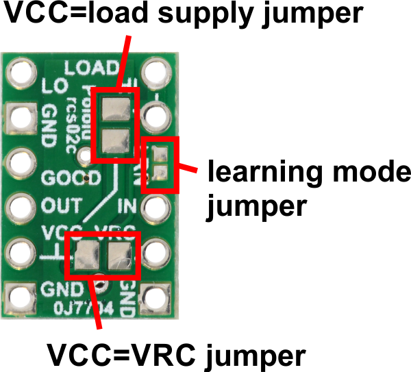
The bottom of the board has jumpers that can be bridged with solder in order connect VCC to VRC or
VCC to LOAD HIGH. These jumpers provide extra flexibility in how the system is powered, and some
examples are given in Section 3.2.
Load interface
The LOAD LOW and LOAD HIGH pins are connections for your load and load supply. The LOAD
LOW pins are normally disconnected from GND, but when the switch activates the MOSFET turns on
and connects LOAD LOW to GND. There is a flyback (also known as a “freewheeling”) diode between
LOAD LOW and LOAD HIGH. The board’s MOSFET can deliver up to 3 A with VCC at 5 V and can
handle load supply voltages up to 30 V. More details on connecting your load and load supply to the
switch can be found in Section 3.2.
Outputs and indicator LED
The RC switch provides feedback about what state it is in via a yellow indicator LED. The LED
behavior is described in Section 8. Status information is also provided by two additional outputs:
• The GOOD pin indicates the presence of a valid RC signal (10–330 Hz pulse rate,
0.5–2.5 ms pulse width).
• The OUT pin indicates whether the MOSFET is on.
When these outputs are high they will be at the same voltage level as VCC. When low, these outputs
will be at 0 V (ground). These outputs do not have resistors in series with them. Each output can
source or sink up to 25 mA.
Pololu RC Switch User’s Guide © 2001–2017 Pololu Corporation
3. RC Switch with Small Low-Side MOSFET Page 12 of 45