
Arduino Library for QTR Reflectance Sensors
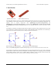


Table Of Contents

Usage Notes
Calibration
This library allows you to use the calibrate() method to easily calibrate your sensors for the particular conditions it will
encounter. Calibrating your sensors can lead to substantially more reliable sensor readings, which in turn can help
simplify your code since. As such, we recommend you build a calibration phase into your application’s initialization
routine. This can be as simple as a fixed duration over which you repeated call the calibrate() method. During this
calibration phase, you will need to expose each of your reflectance sensors to the lightest and darkest readings they will
encounter. For example, if you have made a line follower, you will want to slide it across the line during the calibration
phase so the each sensor can get a reading of how dark the line is and how light the ground is. A sample calibration
routine would be:
#include <PololuQTRSensors.h>
// create an object for your type of sensor (RC or Analog)
// in this example we have three sensors on analog inputs 0 - 2, a.k.a. digital pins 14 - 16
PololuQTRSensorsRC qtr((char[]) {14, 15, 16}, 3);
// PololuQTRSensorsA qtr((char[]) {0, 1, 2}, 3);
void setup()
{
// optional: wait for some input from the user, such as a button press
// then start calibration phase and move the sensors over both
// reflectance extremes they will encounter in your application:
int i;
for (i = 0; i < 250; i++) // make the calibration take about 5 seconds
{
qtr.calibrate();
delay(20);
}
// optional: signal that the calibration phase is now over and wait for further
// input from the user, such as a button press
}
Reading the Sensors
This library gives you a number of different ways to read the sensors.
1. You can request raw sensor values using the read() method, which takes an optional argument that lets you
perform the read with the IR emitters turned off (note that turning the emitters off is only supported by the
QTR-8x reflectance sensor arrays).
2. You can request calibrated sensor values using the readCalibrated() method, which also takes an optional
argument that lets you perform the read with the IR emitters turned off. Calibrated sensor values will always
range from 0 to 1000, with 0 being as or more reflective (i.e. whiter) than the most reflective surface encountered
during calibration, and 1000 being as or less reflective (i.e. blacker) than the least reflective surface encountered
during calibration.
3. For line-detection applications, you can request the line location using the readLine() method, which takes as
optional parameters a boolean that indicates whether the line is white on a black background or black on a white
background, and a boolean that indicates whether the IR emitters should be on or off during the measurement.
readLine() provides calibrated values for each sensor and returns an integer that tells you where it thinks the line
is. If you are using N sensors, a returned value of 0 means it thinks the line is on or to the outside of sensor 0, and
a returned value of 1000 * (N-1) means it thinks the line is on or to the outside of sensor N-1. As you slide your
sensors across the line, the line position will change monotonically from 0 to 1000 * (N-1), or vice versa. This
line-position value can be used for closed-loop PID control.
A sample routine to obtain the sensor values and perform rudimentary line following would be:
Arduino Library for the Pololu QTR Reflectance Sensors © 2001–2009 Pololu Corporation
3. PololuQTRSensors Methods & Usage Notes Page 6 of 8