
User Manual


Prototyping space on the m3pi
expansion PCB.
Note: 3pi pin PB3 doubles as a 3pi motor driver input and an AVR programming pin. We
strongly recommend that you not connect this pin to anything.
By default, pin PC5 is an AVR output whose state depends on what the 3pi is doing with its
line sensors, even with the PC5 jumper removed. Unless you modify the 3pi base firmware
appropriately, do not connect an output to this pin!
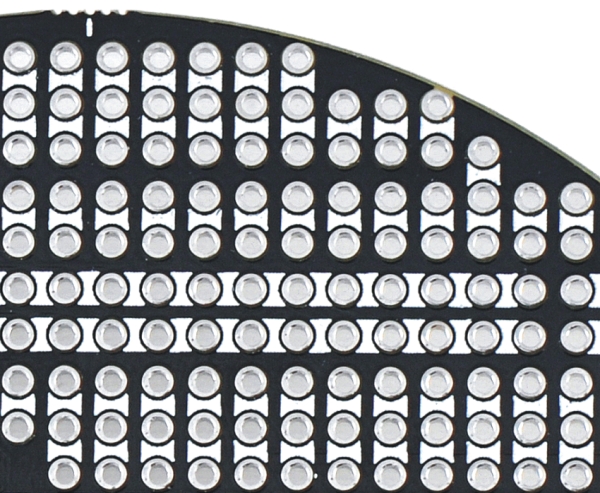
4.j. Prototyping Space
The unused areas of the m3pi expansion PCB have been
configured for use as general-purpose prototyping space. The
through-holes are connected in a breadboard-like pattern
denoted on the top silkscreen by thick, white lines between holes.
You can use this prototyping space to cleanly and easily add
sensors or other custom circuits to your m3pi robot. The traces
that connect the prototyping holes are all on the underside of the
expansion PCB and can be selectively cut to modify the
configuration of the prototyping space.
4.k. m3pi Schematic Diagram
Pololu m3pi User’s Guide © 2001–2017 Pololu Corporation
4. The Expansion Board in Detail Page 38 of 39