
User Manual


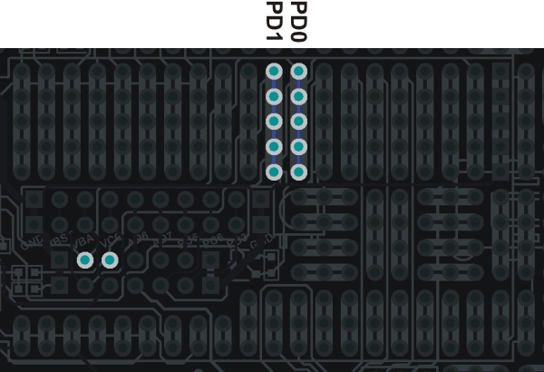
m3pi mbed socket pins that connect to PD0 and PD1 on the 3pi
base.
You can find out more about these I/O lines from section 10.c of the 3pi user’s guide
[https://www.pololu.com/docs/0J21/10.c]. The most relevant part of that section is quoted below:
You can freely use PD0 and PD1 for general-purpose digital I/O, or you can use them for
serial communication with another microcontroller, a serially-controlled device, or a computer
(note that you will need to convert the signal to RS-232 levels or USB to communicate with a
computer).
In addition to PD0 and PD1, the 3pi robot has a limited number of I/O lines that can be used
as inputs for additional sensors or to control additional electronics such as LEDs or servos.
These I/O lines can be accessed through the pads at the center of the 3pi, between the two
motors, labeled PD0, PD1, ADC6, ADC7, and PC5. If you are using an expansion kit, these
lines are brought up to the expansion PCB.
Pins PC5, ADC6, and ADC7 are all connected to 3pi hardware via removable shorting blocks.
By removing the shorting block, you can use these pins for your own electronics. Pin PC5
can be used as either a digital I/O or an analog input. When its shorting block is in place, it
controls the emitters for the IR sensors; when its shorting block is removed, the emitters are
always on. Pin ADC6 is a dedicated analog input that connects to a voltage divider circuit that
monitors the battery voltage when its shorting block is in place, and pin ADC7 is a dedicated
analog input that connects to the user trimmer potentiometer when its shorting block is in
place.
Pololu m3pi User’s Guide © 2001–2017 Pololu Corporation
4. The Expansion Board in Detail Page 37 of 39