
User Manual


soldered to the PCB; the m3pi expansion kit includes this header, but it is not soldered in. If you are
assembling the m3pi expansion kit and want to include an AVRISP header, please make sure to align
it properly: pin 1 on the header, denoted by a triangle in the plastic, must connect to pin 1 on the PCB,
denoted by a caret on the silkscreen and an octagonal pad.
The AVRISP connector is not used to program anything on the m3pi expansion PCB. Rather, it allows
you to turn your mbed into an AVR programmer that can be used to reprogram the AVR on the
3pi base if so desired. Simply upload an appropriate program to the mbed [http://mbed.org/users/
aberk/notebook/avr910-in-system-programming-using-mbed/] and connect the AVRISP header on the m3pi
expansion board to the AVRISP header on the 3pi base using the included 6-pin AVRISP cable. Note
that the target’s VDD is not routed to the mbed but rather to a set of three prototyping pins. We suggest
you connect the AVRISP target VDD to the mbed pin of your choosing and monitor the target voltage
while programming so as to avoid programming an unpowered or under-powered AVR.
Note: Programming an unpowered or under-powered AVR can permanently disable it.
If you own a dedicated AVRISP programmer, we suggest you use it rather than the mbed if you want
to reprogram the AVR on your 3pi.
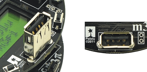
4.h. USB A Connector
m3pi USB A connector.
The m3pi expansion PCB has space for a USB A connector that connects to the mbed’s USB pins
(D+ and D-). The fully-assembled m3pi robot ships with the USB A connector soldered to the PCB; the
m3pi expansion kit includes this connecor, but it is not soldered in.
The USB A connector allows the mbed to act as a USB host and interface directly with USB devices.
For example, you could plug a USB flash drive into your m3pi and have your robot log data to it as it
Pololu m3pi User’s Guide © 2001–2017 Pololu Corporation
4. The Expansion Board in Detail Page 35 of 39