
User Manual


m3pi charge port.
The LEDs are evenly distributed both radially and horizontally, which means they can conceivably be
used for persistence of vision displays when the m3pi robot is spinning in place or driving straight. In
practice, we have found that the robot does not drive fast enough in a straight line for the naked eye
to perceive persistence of vision (though it could still work if you use a camera to take a picture with
a long exposure time as the robot drives), but it does spin fast enough when rotating in place for the
naked eye to perceive persistence of vision displays (see the pictures below).
Pololu m3pi robot writing “HELLO”
with its eight mbed-controlled LEDs as
it spins in place (persistence of
vision).
Pololu m3pi robot writing “HELLO”
with its eight mbed-controlled LEDs as
it spins in place (persistence of
vision).
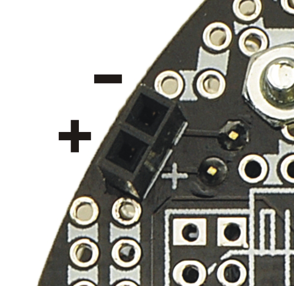
4.f. Charge Port
The m3pi expansion PCB has a two-pin charge port in the front-left
corner of the robot that can be used to recharge your m3pi robot if
you are using rechargeable batteries. The fully-assembled m3pi
robot ships with a female 0.1″ header soldered into this port; the
m3pi expansion kit includes the header but it is not soldered in. The
charge port provides a direct connection to the batteries and can be
used with a charger capable of charging four NiMH or NiCD cells
(depending on what you’re using) in series. The iMAX-B6AC
charger [https://www.pololu.com/product/2588] works well for this
purpose; other such chargers are readily available in hobby stores
for charging electric model airplane battery packs. The positive side
of the batteries is labeled on the charge port by a white “+” on the
PCB silkscreen.
Pololu m3pi User’s Guide © 2001–2017 Pololu Corporation
4. The Expansion Board in Detail Page 33 of 39