
User Manual


section. Please see Section 4.h for more information about the USB A connector.
AVRISP Connector
If you want to use your mbed as an AVR programmer (e.g. to reprogram the microcontroller on the
3pi base), you should solder the shrouded and keyed six-pin (2×3) 0.1″ male header to the m3pi PCB
as shown in the two diagrams at the top of this section. Please note that this header can be installed
two different ways, but only one orientation is correct: pin 1 on the header, denoted by a triangle in the
plastic, must connect to pin 1 on the PCB, denoted by a caret on the silkscreen and an octagonal pad
(and the gap in the shroud faces the LCD cutout). This header will not work if it is installed incorrectly,
so please verify the orientation before you start soldering. Please see Section 4.g for more information
about the AVRISP connector.
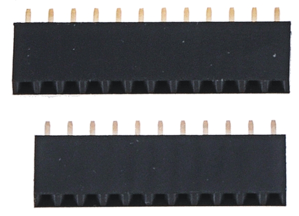
Wixel Socket
If you want to add wireless functionality to your m3pi robot with a Wixel module [https://www.pololu.com/
product/1336] (or if you want to use the Wixel, which is programmable, as the main controller for your
m3pi rather than an mbed), you should solder the included 1×11 and 1×12 0.1″ female headers to
create a Wixel socket as shown in the following picture:
Pololu m3pi User’s Guide © 2001–2017 Pololu Corporation
2. Assembly Page 14 of 39