
User Manual


The m3pi expansion kit includes three pushbuttons that can be used to add a power button and
two general-purpose user buttons to the m3pi expansion PCB. The locations for these buttons are
shown in the two diagrams at the top of this section. See Section 4.c for more information about the
pushbuttons.
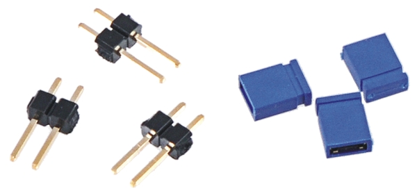
Serial Jumpers
If you want to be able to connect the serial lines of an XBee or Wixel wireless module directly to the
serial lines of the 3pi base (e.g. to use the Wixel as the m3pi’s main controller or to make the m3pi
a serial slave to a remote device), you should solder the three included 1×2 0.1″ male headers to
create the serial jumpers shown in the two diagrams at the top of this section. Be sure to solder the
short ends of the headers to the PCB so that the full extent of the long ends protrude up. The included
shorting blocks can then be placed over the protruding header pins to establish the alternate serial
connections. See Section 4.a for more information about the serial jumpers.
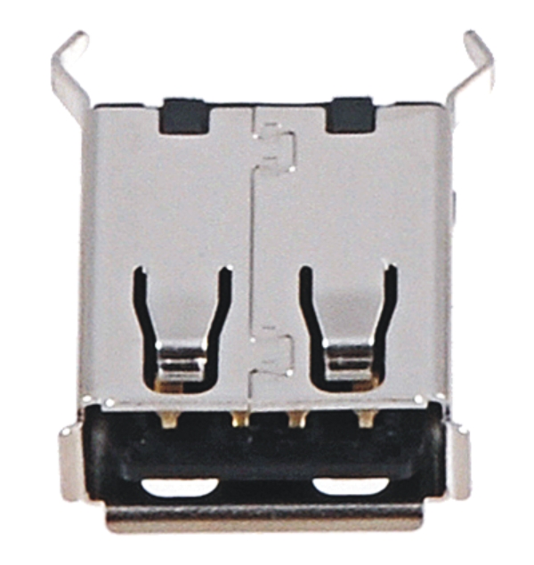
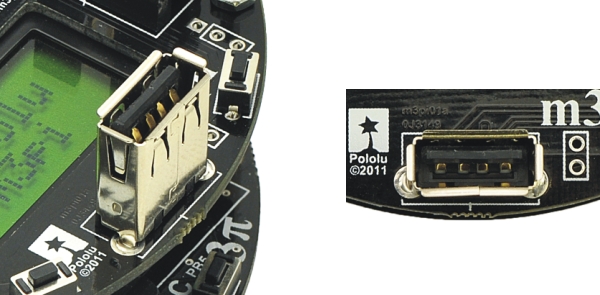
USB A Connector
The m3pi expansion kit includes a USB A header that lets you connect USB devices to your mbed
if it is programmed to act as a USB host. Please note that when installing the USB A connector, the
two large protrusions from the case must be soldered to the PCB along with the four logic pins. These
large protrusions provide structural support for the connector when they are soldered into the large
holes in the PCB. The location for the USB A connector is shown in the two diagrams at the top of this
Pololu m3pi User’s Guide © 2001–2017 Pololu Corporation
2. Assembly Page 13 of 39