
User Manual


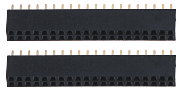
If you want to use an mbed development board [https://www.pololu.com/category/128/mbed-
microcontrollers] as the main controller of your m3pi robot, you should solder the two 2×20 0.1″ female
headers to create a socket for the mbed as shown in the two diagrams at the top of this section. See
Section 4.a for more information on the mbed socket.
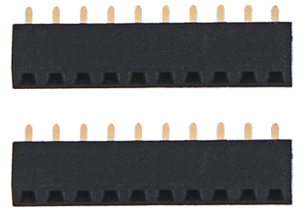
XBee Socket
If you want to use an XBee module to add wireless functionality to your m3pi robot, you should solder
the two 1×10 2mm female headers to create a socket for the XBee as shown in the two diagrams at
the top of this section. Note that the XBee headers are the only included female headers with a 2mm
(0.079″) pitch, so they are noticeably smaller than all the rest. See Section 4.a for more information
on the XBee socket.
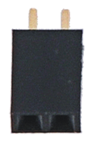
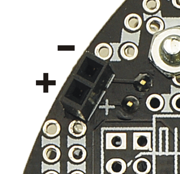
Battery Charge Port
The expansion PCB makes it difficult to reach the battery charge port on the 3pi robot base, so it has
connectors that bring the port up to the expansion PCB for easier access. One of the included 1×2
0.1″ female headers can be used as a battery charge port when soldered to the m3pi expansion PCB
as shown in the two diagrams at the top of this section. See Section 4.f for more information about
the battery charge port.
Pushbuttons
Pololu m3pi User’s Guide © 2001–2017 Pololu Corporation
2. Assembly Page 12 of 39