
User Manual


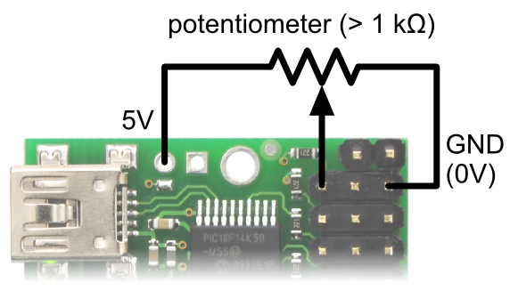
Diagram for connecting a
potentiometer to the Micro Maestro
servo controller.
You can test your input by toggling the button/switch and verifying that the “Position” variable as shown
in the Status tab of the Maestro Control Center reflects the state of your button/switch: it should be
close to 255.75 when the button/switch is inactive and close to 0 when it is active. Now you can read
the state of the button/switch in your script using the GET_POSITION command or over serial using
the “Get Position” command. These commands will return values that are close to 1023 when the
button/switch is inactive and close to 0 when it is active.
Potentiometer
To connect a potentiometer to the Maestro, you must first
decide which channel you would like to use. If you have the
Mini Maestro 18- or 24-channel servo controller, be sure to
pick one of the analog input capable channels (channels
0–11). In the Maestro Control Center, under the Channel
Settings tab, change that channel to Input mode and click
“Apply Settings”. Next, connect the potentiometer to the
Maestro so that the two ends go to GND and 5 V, and the
wiper connects to the signal line of the channel. The picture to
the right shows how to connect a potentiometer to channel 0
on the Micro Maestro 6-channel servo controller. The
potentiometer should have a resistance of at least 1 kilo-ohm so that it does not draw too much current
from the 5V line.
You can test your input by rotating the potentiometer and verifying that the “Position” variable as shown
in the Status tab of the Maestro Control Center reflects the position of the potentiometer: it should
vary between approximately 255.75 and 0. Now you can read the position of the potentiometer in your
script using the GET_POSITION command or over serial using the “Get Position” command. These
commands will return values between approximately 1023 and 0.
LED
Pololu Maestro Servo Controller User’s Guide © 2001–2019 Pololu Corporation
7. Wiring Examples Page 93 of 102