
User Manual


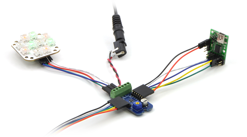
Connecting the Micro Maestro to a chain of
ShiftBars. A single 12V supply powers all of the
devices.
many seconds or minutes can be accomplished:
It is easy to write subroutines for delays of hours, days, weeks, or whatever you want. Keep in mind,
however, that the timer on the Micro Maestro is not as accurate as a stopwatch – these delays could
easily be off by 1%.
Digital output
The digital output feature of the Maestro is
capable of controlling anything from simple
circuits to intelligent devices such as the
ShiftBrite LED Modules [https://www.pololu.com/
product/1222] and ShiftBar LED Controllers
[https://www.pololu.com/product/1242], which use a
simple synchronous serial protocol. In this
example, the clock, latch, and data pins of a
ShiftBrite or ShiftBar are connected to servo
channels 0, 1, and 2, respectively, and these
channels are all configured as outputs. The
subroutine RGB defined here takes 10-bit red,
green, and blue values from the stack, then sends a 32-byte color packet and toggles the latch pin to
update the ShiftBrite with the new color value. The subroutine could be modified to control a larger
chain of ShiftBrites if desired.
1
2
3
4
5
6
7
8
9
10
11
12
13
14
15
16
17
18
19
20
21
# Moves servo 0 back and forth, with a delay of 10 minutes between motions.
begin
4000 0 servo
10 delay_minutes
8000 0 servo
10 delay_minutes
repeat
# delay by a specified number of seconds, up to 65535 s
sub delay_seconds
begin dup while # check if the count has reached zero
1 minus 1000 delay # subtract one and delay 1s
repeat
drop return # remove the 0 from the stack and return
# delay by a specified number of minutes, up to 65535 min
sub delay_minutes
begin dup while
1 minus 60 delay_seconds # subtract one and delay 1min
repeat
drop return # remove the 0 from the stack and return
?
Pololu Maestro Servo Controller User’s Guide © 2001–2019 Pololu Corporation
6. The Maestro Scripting Language Page 87 of 102