
Data Sheet

FinalDatasheet 9 Rev.1.0, 2008-09-18
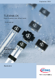
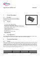
TLE4946-2K
Specification
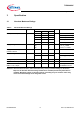
3.2 Operating Range
The following operating conditions must not be exceeded in order to ensure correct operation of the TLE4946-2K.
All parameters specified in the following sections refer to these operating conditions unless otherwise mentioned.
Table 3 Operating Range
Parameter Symbol Values Unit Note/ Test Condition
Min. Typ. Max.
Supply voltage V
S
2.7 – 18 V
Output voltage V
Q
– 0.7 – 18 V
Junction temperature T
j
– 40 – 150 °C
Output current I
Q
0 – 20 mA
3.3 Characteristics
Product characteristics involve the spread of values guaranteed within the specified voltage and ambient
temperature range. Typical characteristics are the median of the production (at V
s
= 12V and T
A
= 25°C ).
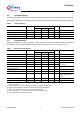
Table 4 Electrical Characteristics
Parameter Symbol Values Unit Note/ Test Condition
Min. Typ. Max.
Supply current I
S
2 4 6 mA V
S
= 2.7 V ... 18 V
Reverse current I
SR
0 0.2 1 mA V
S
= – 18 V
Output saturation voltage V
QSAT
– 0.3 0.6 V I
Q
= 20 mA
Output leakage current I
QLEAK
– 0.05 10 µA for V
Q
= 18 V
Output fall time t
f
– 0.02 1 µs R
L
= 1.2 kΩ;
C
L
= 50 pF
Output rise time t
r
– 0.4 1 µs
Chopper frequency f
OSC
– 320 – kHz
Switching frequency f
SW
0 – 15
1) To operate the sensor at the max. switching frequency, the value of the magnetic signal amplitude must be 1.4 times higher
than for static fields.
This is due to the - 3 dB corner frequency of the low pass filter in the signal path.
1)
kHz
Delay time
2) Systematic delay between magnetic threshold reached and output switching
2)
t
d
– 13 – µs
Output jitter
3) Jitter is the unpredictable deviation of the output switching delay
3)
t
QJ
– 1 – µs
RMS
Typical value for
square wave signal
1
kHz
Power-on time
4) Time from applying V
S
≥ 2.7 V to the sensor until the output state is valid
4)
t
PON
– 13 – µs V
S
≥ 2.7 V
Thermal resistance
5) Thermal resistance from junction to ambient
5)
R
thJA
– 100 K/W