
Allegro ACS714 current sensor datasheet
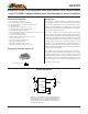


Automotive Grade, Fully Integrated, Hall Effect-Based Linear Current Sensor
with 2.1 kVRMS Voltage Isolation and a Low-Resistance Current Conductor
ACS714
6
Allegro MicroSystems, Inc.
115 Northeast Cutoff, Box 15036
Worcester, Massachusetts 01615-0036 (508) 853-5000
www.allegromicro.com
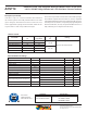
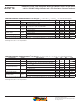
x20A PERFORMANCE CHARACTERISTICS over Range E: T
A
= –40°C to 85°C
1
, C
F
= 1 nF, and V
CC
= 5 V, unless otherwise specified
Characteristic Symbol Test Conditions Min. Typ. Max. Units
Optimized Accuracy Range I
P
–20 – 20 A
Sensitivity Sens Over full range of I
P
, T
A
= 25°C 96 100 104 mV/A
Noise V
NOISE(PP)
Peak-to-peak, T
A
= 25°C, 100 mV/A programmed Sensitivity,
C
F
= 47 nF, C
OUT
= open, 2 kHz bandwidth
–11–mV
Zero Current Output Slope
ΔI
OUT(Q)
T
A
= –40°C to 25°C – –0.34 – mV/°C
T
A
= 25°C to 150°C – –0.07 – mV/°C
Sensitivity Slope
ΔSens
T
A
= –40°C to 25°C – 0.017 – mV/A/°C
T
A
= 25°C to 150°C – –0.004 – mV/A/°C
Electrical Output Voltage V
OE
I
P
= 0 A –30 – 30 mV
Total Output Error
2
E
TOT
I
P
= ±20 A
,
T
A
= 25°C – ±1.5 – %
1
Device may be operated at higher primary current levels, I
P
, and ambient temperatures, T
A
, provided that the Maximum Junction Temperature,
T
J
(max), is not exceeded.
2
Percentage of I
P
, with I
P
= 20 A. Output filtered.
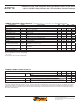
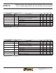
x20A PERFORMANCE CHARACTERISTICS over Range L: T
A
= –40°C to 150°C
1
, C
F
= 1 nF, and V
CC
= 5 V, unless otherwise specified
Characteristic Symbol Test Conditions Min. Typ. Max. Units
Optimized Accuracy Range I
P
–20 – 20 A
Sensitivity Sens
Over full range of I
P
, T
A
= 25°C – 100 – mV/A
Over full range of I
P
, T
A
= –40°C to 150°C 94 – 104 mV/A
Noise V
NOISE(PP)
Peak-to-peak, T
A
= 25°C, 100 mV/A programmed Sensitivity,
C
F
= 47 nF, C
OUT
= out, 2 kHz bandwidth
–11–mV
Zero Current Output Slope
ΔI
OUT(Q)
T
A
= –40°C to 25°C – –0.34 – mV/°C
T
A
= 25°C to 150°C – –0.07 – mV/°C
Sensitivity Slope
ΔSens
T
A
= –40°C to 25°C – 0.017 – mV/A/°C
T
A
= 25°C to 150°C – –0.004 – mV/A/°C
Electrical Output Voltage V
OE
I
P
= 0 A –40 – 40 mV
Total Output Error
2
E
TOT
I
P
= ±20 A
,
T
A
= 25°C – ±1.5 – %
I
P
= ±20 A
,
T
A
= –40°C to 150°C –5 – 5 %
1
Device may be operated at higher primary current levels, I
P
, and ambient temperatures, T
A
, provided that the Maximum Junction Temperature,
T
J
(max), is not exceeded.
2
Percentage of I
P
, with I
P
= 20 A. Output filtered.