
Allegro ACS714 current sensor datasheet


Automotive Grade, Fully Integrated, Hall Effect-Based Linear Current Sensor
with 2.1 kVRMS Voltage Isolation and a Low-Resistance Current Conductor
ACS714
15
Allegro MicroSystems, Inc.
115 Northeast Cutoff, Box 15036
Worcester, Massachusetts 01615-0036 (508) 853-5000
www.allegromicro.com
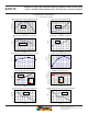
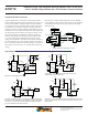
Package LC, 8-pin SOIC
Copyright ©2006-2009, Allegro MicroSystems, Inc.
The products described herein are manufactured under one or more of the following U.S. patents: 5,619,137; 5,621,319; 6,781,359; 7,075,287;
7,166,807; 7,265,531; 7,425,821; or other patents pending.
Allegro MicroSystems, Inc. reserves the right to make, from time to time, such de par tures from the detail spec i fi ca tions as may be required to per-
mit improvements in the per for mance, reliability, or manufacturability of its products. Before placing an order, the user is cautioned to verify that the
information being relied upon is current.
Allegro’s products are not to be used in life support devices or systems, if a failure of an Allegro product can reasonably be expected to cause the
failure of that life support device or system, or to affect the safety or effectiveness of that device or system.
The in for ma tion in clud ed herein is believed to be ac cu rate and reliable. How ev er, Allegro MicroSystems, Inc. assumes no re spon si bil i ty for its use;
nor for any in fringe ment of patents or other rights of third parties which may result from its use.
For the latest version of this document, visit our website:
www.allegromicro.com
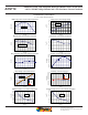
C
SEATING
PLANE
1.27 BSC
GAUGE PLANE
SEATING PLANE
A
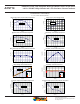
Terminal #1 mark area
B
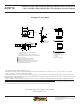
Reference land pattern layout (reference IPC7351
SOIC127P600X175-8M); all pads a minimum of 0.20 mm from all
adjacent pads; adjust as necessary to meet application process
requirements and PCB layout tolerances
B
D
C
21
8
Branding scale and appearance at supplier discretion
C
SEATING
PLANE
C0.10
8X
0.25 BSC
1.04 REF
1.75 MAX
For Reference Only; not for tooling use (reference MS-012AA)
Dimensions in millimeters
Dimensions exclusive of mold flash, gate burrs, and dambar protrusions
Exact case and lead configuration at supplier discretion within limits shown
4.90 ±0.10
3.90 ±0.10 6.00 ±0.20
0.51
0.31
0.25
0.10
0.25
0.17
1.27
0.40
8°
0°
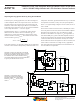
N = Device part number
P = Package Designator
T = Device temperature range
A = Amperage
L = Lot number
Belly Brand = Country of Origin
NNNNNNN
LLLLL
1
PPT-AAA
A
Standard Branding Reference View
21
8
PCB Layout Reference View
C
0.65
1.27
5.60
1.75
Branded Face