PMS 419 POLARIS POWER™ P1000i P2000i Operator’s Manual (Australian models) Failure to properly follow the instructions and precautions in this manual can result in property damage, serious injury or DEATH! For your nearest Polaris supplier, call 0393945610 or visit www.polarispower.com.au Polaris Sales Australia Pty Ltd., (ABN 62088081949) of Locked Bag 2006, Sunshine Post Shop, Sunshine, Victoria, 3020 Australia Part No.
TABLE OF CONTENTS Introduction . . . . . . . . . . . . . . . . . . . . . . . . . . . . 2 Safety . . . . . . . . . . . . . . . . . . . . . . . . . . . . . . . . . 7 Controls and features . . . . . . . . . . . . . . . . . . . 16 First Use Instructions . . . . . . . . . . . . . . . . . . . 22 Pre-Operation Inspection . . . . . . . . . . . . . . . . 25 Operation . . . . . . . . . . . . . . . . . . . . . . . . . . . . . 26 Maintenance . . . . . . . . . . . . . . . . . . . . . . . . . . .
INTRODUCTION Welcome Thank you for purchasing a POLARIS POWERTM Generator, and welcome to our world-wide family of POLARIS owners. Here at POLARIS we proudly produce an exciting line of utility and recreational products.
INTRODUCTION Intended Use The POLARIS Power Generator is intended to supply power for appliances. Such items include, but are not limited to: • Furnace fans • Sump pumps • Dishwashers • Hotplates / Stoves • Lamps • Fans • Washing machines • Garage door openers • Water heaters • Televisions • Refrigerators • Computers Appliances that use more than recommended amount (see page 62) of combined power consumption should not be connected to this generator.
INTRODUCTION Safety Precautions Failure to follow recommended precautions and procedures could result in severe injury or death. Always heed all safety precautions and follow all operation, inspection, and maintenance procedures outlined in this manual. Please read the POLARIS P1000i/P2000i Generator Owner’s Manual. This manual contains information essential to safe operation and proper maintenance of the generator.
INTRODUCTION Warnings, Cautions and Notices Signal Words and Safety Terms The following signal words and symbols appear throughout this manual. Your safety, and the safety of others, is involved when these words and symbols are used. Become familiar with their meaning before reading the manual. A safety alert warning indicates a hazardous situation which, if not avoided, may result in death or serious injury.
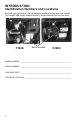
INTRODUCTION Identification Numbers and Locations Record your generator’s identification numbers in the space provided. The model and serial number decal is located inside the service door.
SAFETY Safety Warnings and Precautions IMPORTANT SAFEY INSTRUCTIONS. SAVE THESE INSTRUCTIONS. Failure to follow recommended precautions and procedures could result in severe injury or death. Always read all safety precautions and follow all operation, inspection, and maintenance procedures outlined in this manual. General • Read and understand all of the safety and operating information in this manual and on the product before using the machine. Use the generator only as described in this manual.
SAFETY Safety Warnings and Precautions Before and During Operation • Do not operate the generator in exposed locations where it will be subjected to wet conditions. • Do not touch the generator with wet hands, as this may cause severe electric shocks. • Do not pour water directly over the generator or wash it. • Do not use or store the generator in the rain or snow. • Do not cover the generator when in use.
SAFETY Safety Warnings and Precautions Fire Safety • Keep the generator away from buildings, other equipment, and combustible materials during operation. • Do not enclose the generator in any structure. • Keep children and pets away from generator. • Exhaust system components are very hot during and after use. Hot components can cause burns and fire. Do not touch the hot exhaust system components. Always keep combustible materials away from the exhaust system.
SAFETY Safety Warnings and Precautions Fuel Safety Petrol is highly flammable and explosive under certain conditions. Always use caution when handling petrol. • Petrol is extremely flammable, and petrol vapor can explode. Before refueling allow the engine to cool completely if the generator has been in operation. • Always store petrol in an approved container. • Always refuel outdoors or in a well-ventilated area away from any combustible materials.
SAFETY Safety Warnings and Precautions Carbon Monoxide Safety Generator exhaust contains Carbon Monoxide (CO) vapors. Exposure to Carbon Monoxide by people or pets can result in SEVERE INURY or DEATH. ALWAYS operate generate according to guidelines in labels and this manual. • This portable generator runs on petrol. The generator exhaust vapor contains carbon monoxide (CO). • Carbon monoxide is odorless. You cannot smell it. • Carbon monoxide is colorless. You cannot see it.
SAFETY Safety Warnings and Precautions Electrical Safety This generator produces high voltage electricity. • The generator produces enough electric power to cause serious shock or electrocution if misused. • Always connect the generator to a suitable ground circuit. • When servicing the generator, disconnect the spark plug wire and place it where it cannot contact the plug. Turn the engine switch to the OFF position. • Do not check for a spark with the plug removed. Use only approved spark plug testers.
SAFETY Safety Warnings and Precautions Extension Cord Information • Read the manufacturer starting and running wattage details and operating instructions for the device(s) and appliance(s) that will be used. Often this information can be found in the owner's manual or on specification decals on the device or appliance. • POLARIS recommends using only U.L. (Underwriters Laboratories, Inc.) approved extension cords labeled with the use, size, and wattage rating.
SAFETY Safety Labels and Locations Safety and warning decals have been placed on the generator for your protection. Read and follow the instructions of the decals and warnings on the generator carefully. If any of the decals depicted in this manual differ from the decals on your generator, always read and follow the instructions of the decals on the generator. Carbon Monoxide Warning Using a generator indoors CAN KILL YOU IN MINUTES. The carbon monoxide warning is located on top of the generator.
SAFETY Safety Labels and Locations Improper Generator use can result in SEVERE INJURY or DEATH. Read the OWNER’S MANUAL. Follow all Instructions and Warnings. Petrol is flammable and explosive. Severe burns can result. ALWAYS stop the engine and let cool down before refueling. ALWAYS check for fuel leaks and wipe up any spills. ALWAYS turn the fuel to OFF when not in use. NEVER handle petrol indoors. NEVER overfill the fuel tank. Generator exhaust contains poisonous Carbon Monoxide (CO) vapors.
CONTROLS AND FEATURES Generator Components: A I H D F E C G ITEM NOMENCLATURE J B DESCRIPTION A Spark Plug Cap Remove the top to access the spark plug B Control Panel Generator controls C Air Filter Protects the air flow to the carburetor from becoming obstructed with debris D Oil Dipstick Measures oil level in the engine E Carburetor Vent Hose Atmospheric vent F Carburetor Drain Hose Drains fuel from the carburetor G Starter Recoil Grip Causes the recoil starter to crank the engi
CONTROLS AND FEATURES Control Panel Components: T U K Q N M U Q R N R S M S O O P P1000i ITEM T K NOMENCLATURE P P2000i DESCRIPTION K SMART Throttle Switch Automatically reduces engine speed when loads are shut off or disconnected M DC Fuse Protector Protects DC charging circuit from overloads N 12V DC Receptacle Charges 12V DC batteries O Ground Terminal Provides ground for non-conductive metal parts and receptacle ground terminals P 240V AC Receptacles Provides two con
CONTROLS AND FEATURES Choke Lever Move the choke lever (H) to the START position when starting a cold engine. Slowly move the choke lever to the RUN position as the engine RPM stabilizes. Fuel Tank Cap Vent Lever ON When the engine is well-cooled and not in use, the fuel tank cap vent lever (I) must be placed in the OFF position to reduce the possibility of fuel leakage. The vent lever must be in the ON position to allow the engine to operate.
CONTROLS AND FEATURES SMART Throttle Switch The SMART throttle switch (K) automatically reduces engine speed when loads are shut off or disconnected. The engine returns to the proper speed to power the electrical load when appliances are turned ON or reconnected. Press the SMART throttle switch to the OFF position to reduce voltage changes when high electrical loads are simultaneously connected or when using the DC output.
CONTROLS AND FEATURES Ground Terminal The ground terminal (O) connects to the frame of the generator, metal parts that do not conduct current, and ground terminals of each receptacle. Consult a qualified electrician, electrical inspector, or local agency having jurisdiction for local codes or ordinances for the intended use of the generator before using the ground terminal. AC Receptacles The AC receptacles (P) provide connections for properly rated AC appliances, see page 62 for specifications.
CONTROLS AND FEATURES Overload Protector Reset Switch Should the generator overload, AC power will be cut off but the engine will stay running. Correct the overload condition and then press the overload reset switch (T) on the front panel. AC power will be restored immediately. Parallel Receptacles Two POLARIS parallel ready generators can be connected together to increase the total power available to a load, using the parallel receptacles (U).
FIRST USE INSTRUCTIONS Adding Engine Oil Failure to use the recommended 4-stroke engine oil may result in engine damage, see page 62 for recommended oil and capacity. 1. Place generator on flat, level surface. Open the service door. See page 46. 2. Remove the oil filler cap / A dipstick (A). 3. Fill the engine crankcase with the specified amount of engine oil. See page 62. 4. Insert the dipstick into the filler neck, without screwing it in. 5.
FIRST USE INSTRUCTIONS Fuel Recommendation POLARIS recommends the use of 91 octane fuel or higher. Do not use fuel containing more than 10% ethanol. Do not use petrol containing methanol. IMPORTANT: Operating the generator with an obstructed fuel system will result in serious engine damage. Perform maintenance as recommended. IMPORTANT: Thoroughly read “Safety” section and all safety information when handling fuel.
FIRST USE INSTRUCTIONS Adding Fuel 1. Remove the fuel tank cap (A). C Loosen Tighten A 2. Fill carefully to avoid spilling fuel on the fuel tank strainer (B). Do not overfill the fuel tank (there should be no fuel above the upper limit mark). B 3. Securely tighten the fuel tank cap (A). 4. Position the fuel tank vent lever (C) OFF for storage or transport, or ON to operate the generator. 5. Move generator away from the fueling source and site before starting the engine.
PRE-OPERATION INSPECTION Note: Always perform the recommended pre-operation inspections before each use. Always perform the inspections at the beginning of a project and when removing the generator from storage. Failure to perform the recommended pre-operation inspections could result in minor or moderate injury or property damage. When inspection reveals the need for adjustment, replacement, or repair, perform service promptly.
OPERATION Safe Operating Precautions Fuel Recommendations The generator engine is certified to operate on regular unleaded petrol with a pump octane rating of 91 or higher. Never use stale or contaminated petrol or an oil /petrol mixture. Avoid getting dirt or water in the fuel tank. The use of regular unleaded petrol containing no more than 10% ethanol (E10) by volume is permitted. Do not use petrol containing methanol.
OPERATION Safe Operating Precautions Refueling 1. Remove the fuel tank cap (A). A Loosen Tighten 2. Fill carefully to avoid spilling fuel or exceeding the bottom of the fuel tank strainer (B). 3. Securely tighten the fuel tank cap (A) until it clicks. 4. Position the fuel tank vent lever OFF for storage or transport, or ON to operate the generator, if equipped. 5. Move generator at least 10 feet (3 meters) away from the fueling source and site before starting the engine.
OPERATION Safe Operating Precautions Before Starting the Engine Read, understand, and follow the Safety Section of this manual. 1. Ensure the generator is away from the fueling source. 2. The generator will vibrate during operation. Place the generator in a dry location and on a flat, level surface. 3. Unplug all power cords and extension cords from the generator. DANGER Using a generator indoors CAN KILL YOU IN MINUTES. Generator exhaust contains carbon monoxide. This is a poison you cannot see or smell.
OPERATION Safe Operating Precautions Starting the Engine 4. Position the engine switch to ON. ON OFF 5. Lightly pull the starter recoil grip until resistance is felt. Then, firmly pull straight out. Do not allow starter grip to snap back against the generator. Return it gently to prevent damage to the starter. 6. If the choke lever was positioned to START the engine, gradually move it to RUN as the engine warms up. 7.
OPERATION Safe Operating Precautions Stopping the Engine In case of emergency, position the engine switch to OFF to stop the engine. Under normal conditions, perform the following procedure. 1. Shut off or disconnect all appliances connected to the generator. 2. Position the engine switch to OFF. ON OFF 3. Allow the engine to cool and position the fuel tank cap vent lever to OFF.
OPERATION Safe Operating Precautions AC Operation Before connecting a device or power cord to the generator, ensure it is in good condition. Faulty appliances or power cords can create a potential for electrical shock. If an appliance begins to operate abnormally, becomes sluggish, or suddenly stops, immediately shut it off. Disconnect the appliance and determine whether the problem is the appliance or if the rated load capacity of the generator has been exceeded.
OPERATION Safe Operating Precautions AC Capacity In case of substantial overloading, the electronic circuit protector will activate. Slightly overloading the generator or running at maximum power operation (30 minutes) may not switch the circuit ON, but will shorten the service life of the generator. Maximum power is: (see page 62) For continuous operation, do not exceed rated power: (see page 62) Consider the total power requirements of all connected devices.
OPERATION Safe Operating Precautions AC Capacity Note: Typical wattages are listed in the table below. Before plugging any device into the generator, verify the manufacturer-listed wattage on the device.
OPERATION Safe Operating Precautions Power Management DEVICE ADDITIONAL RUNNING STARTING (SURGE) (RATED) WATTS WATTS Paint Sprayer 360 1080 Radio 300 300 Total Running (Rated) Watts = 660 Additional Starting Surge Watts = 1380 Total Generator Output Required = 2040 Ensure the combined electrical rating of the powered device(s) do not exceed the maximum allowed by the generator. Never exceed the maximum power rating of the generator.
OPERATION Safe Operating Precautions DC Operation Connecting the Battery Charging Cable (included) 1. Position the SMART throttle switch to OFF. 2. Disconnect the vehicle ground cable from the negative (-) battery terminal. 3. Plug the battery charging cable into the DC receptacle. See page 19. 4. Connect the red lead of the battery charging cable to the positive (+) battery terminal and then the black lead to negative (-) battery terminal.
OPERATION Safe Operating Precautions DC Operation Disconnecting the Battery Charging Cable: 1. Stop the generator. 2. Disconnect the black lead of the battery charging cable from the negative (-) battery terminal and then the lead from the positive (+) battery terminal. 3. Unplug the battery charging cable from the DC receptacle. See page 19. 4. Connect the vehicle battery ground cable to the negative (-) battery terminal.
OPERATION Safe Operating Precautions Standby Power Improper connection to a building electrical system can allow current from the generator to back feed into the utility lines. Such back feed may electrocute utility company workers or others who contact the lines during a power outage. Additionally, the generator may explode, burn, or cause fires when utility power is restored. Consult the utility company or a qualified electrician prior to making any power connections.
OPERATION Parallel Generator Operation Parallel operation features, kits sold separately. Two POLARIS parallel ready generators can be connected together to increase the total power available to a load. The system seamlessly matches frequency and automatically evenly distributes the load to each generator so one is not overloaded. Operating the generators in parallel has 0.9 power de-rate factor.
OPERATION Parallel Generator Operation Parallel operation procedure While operating in parallel, the only AC output is through the receptacle on the parallel cable box. Do not use the receptacles on the control panel of the generator. The required output of the electrical appliance cannot exceed the rated output of parallel generators. Shutting off the generators 1. Turn off the power of electrical appliance then, pull out the receptacle plug. 2. Turn off the two generators. 3.
OPERATION High Altitude Use Carburetor Modification When carburetor has been modified for high altitude operation, the airfuel mixture will be too lean for low altitude use and may cause engine damage. At high altitude, the standard carburetor air-fuel mixture will be excessively rich. Performance will decrease and fuel consumption will increase. A very rich mixture will also foul the spark plug and cause hard starting.
OPERATION Emission Control System Information Source of Emissions Exhaust gas contains carbon monoxide, nitrous oxide (NOx), and hydrocarbons. It is very important to control the emissions of NOx and hydrocarbons as they are a major contributor to air pollution. Carbon monoxide is a poisonous gas. The generator engine utilizes a precise airfuel ratio and emission control system to reduce the emissions of carbon monoxide, NOx, hydrocarbons.
OPERATION Emission Control System Information Problems Affecting Emissions If aware of any of the following, have the engine inspected and repaired by an authorized POLARIS supplier: • Hard starting or stalling after starting • Rough idle • Shut down or backfire after applying an electrical load • Afterburning (backfiring) • Black exhaust smoke or high fuel consumption Replacement Parts The emission control system on the engine was designed, built, and certified to conform to applicable emission regulation
MAINTENANCE Importance of Maintenance Good maintenance is essential for safe and economical operation. Proper maintenance will also help reduce air pollution. To ensure the longevity of the generator, the following pages include a periodic maintenance schedule and inspection and maintenance procedures. Other, more difficult tasks, require special tools and expertise provided by a POLARIS technician or other qualified mechanic. The maintenance schedule applies to normal operating conditions.
MAINTENANCE Maintenance Safety Personal safety is critical when attempting to service the generator. Improperly installed or adjusted components can make the generator unstable or dangerous. Improperly installed electrical components can cause engine or electrical systems failure. In either event, damage or serious injury could result. If you do not have the time, tools, and/or expertise necessary to complete a procedure properly, please see your POLARIS supplier for service.
MAINTENANCE Periodic Maintenance • Always stop the engine before servicing. Disconnect all devices and extension cords to avoid receiving an electrical shock. • Periodic checks and maintenance are very important for keeping the generator in good condition. • Inspect, clean, lubricate, adjust, and replace parts as necessary. When inspection reveals the need for replacement parts, use POLARIS Genuine parts available from your POLARIS supplier.
MAINTENANCE Opening the Service Door Use the following steps to open the generator service door and gain access to the inner components. Before performing any maintenance, the fuel tank cap vent lever and engine switch should be positioned to OFF. See page 18. 1. Position the fuel tank cap vent A lever (A) to OFF, if equipped. See page 18. 2. Position the engine switch (B) to OFF. See page 18. 3. Loosen the service door screw (C). 4. Open the service door (D). D 5. Expose the generator inner C components.
MAINTENANCE Initial Maintenance 20-Hour Initial Break-In In order to insure the optimum output and the maximum service life of the generator, the generator should run at a 50% load for the first 20 hours 1. Perform “Oil Change”. 2. Perform “Air Filter Inspection”. Replace as needed. Fuel System Petrol is highly flammable and explosive, and can cause serious injury or death. Stop the engine and keep heat, sparks, and flame away. Handle fuel only outdoors. Wipe up spills immediately.
MAINTENANCE Fuel System 2. Remove the fuel tank strainer (B) from the fuel tank. 3. Remove any foreign objects or debris from the fuel tank strainer (B). 4. Inspect the fuel tank strainer (B) for damage. Replace as needed. 5. Install the fuel tank strainer (B) into the fuel tank. 6. Securely tighten the fuel tank cap (A) until it clicks. 7. Position the fuel tank cap vent lever (C) OFF for storage or transport, or ON to run the generator.
MAINTENANCE Engine Oil Oil Recommendation Oil directly affects performance and service life. Use a 4-stroke automotive detergent oil. POLARIS 5W-30 Engine Oil is recommended for this generator. The SAE oil viscosity and service category are in the API label on the oil container. POLARIS recommends the use of API service category “SJ” or later, equivalent oil. Oil Level Inspection Failure to use the proper 4-stroke engine oil may result in engine damage.
MAINTENANCE Engine Oil Oil Change Procedure Oil may be hot. Do not allow hot oil to come into contact with skin, as serious burns may result. Note: Drain the oil while the engine is warm to assure rapid and complete draining. 1. Start the engine and allow it to run for a few minutes. Stop the engine. 2. Position engine switch and fuel cap ON vent lever to OFF. OFF 3. Open the service door. See page 46. 4. Place a drain pan beneath the generator for used oil. 5.
MAINTENANCE Engine Oil Oil Change Procedure 7. Fill the oil to the high limit mark (B) B on the dipstick (A). 8. Start the engine and let it run for 1 or 2 minutes. Stop the engine and look for leaks. 9. Re-check the oil level on the dipstick (A) and add oil as needed to bring the level to the upper mark (B) on the dipstick. 10. Re-install the dipstick (A). 11. Re-install the service door. 12. Wash hands with soap and water after handling used oil.
MAINTENANCE Air Filters Operating the engine without air filters or with a damaged air filters will allow debris to enter the engine, causing rapid wear. Air Filter Inspection Note: An obstructed air filter restricts air flow to the carburetor. To prevent carburetor malfunction, regularly service the air filter. Service more frequently when operating the generator in extremely dusty areas. 1. Open the service door. See page 46. 2. Loosen the cover screw (A) and remove the air filter cover (B). 3.
MAINTENANCE Air Filters Air Filter Cleaning Note: If operating the generator in a very dust area, clean the air filters more frequently than specified in the Periodic Maintenance Chart. 1. Wash the air filters (C) in warm water and detergent, rinse, and allow to completely dry; or clean with a high flash point solvent and allow to completely dry. 2. Soak the elements in clean engine oil and squeeze out the excess oil. 3. Wipe debris from the air filter housing and air filter cover (B) using a moist towel.
MAINTENANCE Spark Plug Spark Plug Inspection and Replacement Using a non-recommended spark plug can result in serious engine damage. Always use recommended spark plugs. Note: In order to service the spark plug, a commercially available spark plug wrench is required. Refer to the “Specification” (page 62) for the recommended spark plug type. Always torque the spark plug to specification. Note: To ensure proper engine operation, the spark plug must be free of deposits and properly gapped.
MAINTENANCE Spark Plug Spark Plug Inspection and Replacement 2. Remove the spark plug cap (B). 3. Clean any dirt from around the base of the spark plug. 4. Using a spark plug wrench, remove the spark plug. B 5. Inspect the electrode for wear and carbon buildup. Look for a sharp outer edge with no rounding or erosion of the electrode. Inspect electrode for wear and buildup 6. Inspect spark plug. Replace if electrode is worn or if the insulator is cracked, chipped, or fouled. 7.
TRANSPORTATION AND STORAGE Transportation Transporting the Generator A hot engine or exhaust system can cause severe burns and ignite flammable material. Ensure adequate time for cooling before storage or transportation. When operating or transporting the generator, be sure it is kept upright. If the generator tilts, fuel may leak. Be sure the fuel tank cap is tight during transportation. Do not operate the generator while transporting or while it is in a vehicle.
TRANSPORTATION AND STORAGE Storage Storage Preparation Petrol is highly flammable and explosive and can cause serious injury. Stop the engine and keep heat, sparks, and flame away. Handle fuel only outdoors. Wipe up spills immediately. Note: Long-term storage of the generator will require some additional preventative measures to guard against deterioration. If fuel is kept in the generator, ensure that the engine is run for at least 30 minutes per month in order to ensure an easy start in emergencies. 1.
TRANSPORTATION AND STORAGE Storage Accessing the Fuel Tank 1. Position the fuel tank vent lever (A) to OFF (see page 18) to reduce leakage possibilities. Remove the fuel tank cap (B). A Loosen Tighten B 2. Remove the fuel tank strainer (C) from the fuel tank. Remove debris as needed. 3. When maintenance is complete, reinstall the fuel tank strainer (C) into the fuel tank. 4. Securely tighten the fuel tank cap (B) until it clicks.
TRANSPORTATION AND STORAGE Storage Draining Fuel from the Fuel Tank and Carburetor Petrol is highly flammable and explosive and can cause serious injury. Stop the engine and keep heat, sparks, and flame away. Handle fuel only outdoors. Wipe up spills immediately. Do not spill fuel when draining the fuel tank. Spilled fuel is a fire hazard, causes environmental damage, and can cause damage to paint and plastic. Wipe up spills immediately.
TRANSPORTATION AND STORAGE Storage 9. Remove spark plug cap (C). C 10. Pull starter grip (D) three to four times to drain the petrol from the fuel pump and into a suitable container. 11. Position engine switch (E) to OFF (see page 18) and tighten the carburetor drain screw. 12. Re-install spark plug cap on the spark plug securely. 13. Re-install the top of the unit and the service door. D E ON OFF Fogging the Engine 1. Remove the top of the unit to access the spark plug, see page 54. 2.
TRANSPORTATION AND STORAGE Storage Fogging the Engine 5. Ensure that the spark plug sealing washer is in good condition and hand-tighten the spark plug to prevent cross-threading. Torque to specification on page 62. 6. Re-install the spark plug cap (A) and the top of the unit. Storage Precautions Do not store the generator outdoors in the cold weather when not in use. • Select a well-ventilated storage area away from any flame-operated appliance (i.e., furnace, water heater, or clothes dryer).
SPECIFICATIONS General Specifications ALTERNATOR Model P1000i P2000i Rated Frequency (Hz) 50 Rated Voltage (V) 240 Rated Current (A) 3.75 Max Current (A) 4.17 6.67 8.33 DC Output Voltage 12V (5A) Rated Output 900 W 1600 W Maximum Output 1000 W 2000 W Phase Single ENGINE Model KG144 Type Single cylinder, 4 stroke, vertical shaft, air-cooled, OHV KG158 Displacement (cc) 58 106 POLARIS 5W-30 Generator Oil Engine Oil Engine Oil Capacity qt (L) (0.25 or 0.
SPECIFICATIONS POLARIS Lubricants and Maintenance Products ENGINE OIL PART NUMBER 2879383 DESCRIPTION POLARIS 5W-30 Generator Oil (1 Quart) (32 oz.) GREASE / SPECIALIZED LUBRICANTS 2871329 Dielectric Grease (Nyogel™) ADDITIVES 2871326 Premium Carbon Clean / Fuel Stabilizer (12 oz.
WIRING DIAGRAMS P1000i Wiring Diagram Red Red Green Yellow green Purple Orange Blue Yellow green Black White Blue Orange Purple Yellow green Green Red Gray Brown Yellow green Single-phase receptacle White Ignition coil Black Black White Brown Gray Red Red Smart Throttle Switch Red Red Spark plug Secondary winding White Black Inverter module Stop switch Black Yellow Trigger winding Blue Reset switch Low oil pressure switch Pink(Black) Orange(Red) Ignition winding Primary
WIRING DIAGRAMS P2000i Wiring Diagram White Secondary winding White Inverter Module Stop switch Black Black Primary winding Black Red Black Black White Brown Gray Red Red Smart Throttle Switch Trigger winding Yellow Red Red Low oil pressure switch Blue Reset switch Ignition winding Pink(Black) Rectifier Orange(Red) Blue Blue DC receptacle Black Red Charging winding Stepping motor Spark plug Ignition coil Blue Yellow green Orange Purple Yellow green Green Red Single-phase recep
TROUBLESHOOTING Troubleshooting Symptoms Engine Will Not Turn Over POSSIBLE CAUSE SOLUTION Starter recoil damage Take the generator to an authorized POLARIS servicing supplier or refer to the service manual Internal engine damage Take the generator to an authorized POLARIS servicing supplier or refer to the service manual Engine Turns Over, but Will Not Start POSSIBLE CAUSE SOLUTION Out of fuel Refuel Water is present in the fuel Drain the fuel system and refuel Old or non-recommended fuel Drai
TROUBLESHOOTING Troubleshooting Symptoms Engine Lacks Power POSSIBLE CAUSE Air filter restricted SOLUTION Clean or replace air filter(s) Bad fuel; generator stored Drain the fuel system and refuel without treating or draining petrol, or refueled with bad petrol Mechanical failure Take the generator to an authorized POLARIS servicing supplier or refer to the service manual Engine Backfires POSSIBLE CAUSE SOLUTION Weak spark from spark plug Inspect, clean, and / or replace spark plug Incorrect spark plu
TROUBLESHOOTING Troubleshooting Symptoms Engine Pings or Knocks POSSIBLE CAUSE SOLUTION Poor quality or low octane fuel Replace with recommended fuel Incorrect ignition timing Take the generator to an authorized POLARIS servicing supplier or refer to the service manual Incorrect spark plug gap or heat range Set gap to specification or replace spark plug Engine Runs Irregularly, Stalls, or Misfires POSSIBLE CAUSE SOLUTION Fouled or defective spark plug Inspect, clean, and / or replace spark plug
TROUBLESHOOTING Troubleshooting Symptoms POSSIBLE LEAN FUEL CAUSE Low or contaminated fuel SOLUTION Add fuel or drain the fuel system and refuel Kinked or plugged fuel tank Inspect and replace vent Low octane fuel Drain the fuel system and refuel Carburetor jetting incorrect Take the generator to an authorized POLARIS servicing supplier or refer to the service manual POSSIBLE RICH FUEL CAUSE SOLUTION Incorrect fuel / fuel is very high octane Drain the fuel system and refuel Stopping / starting wit
TROUBLESHOOTING Troubleshooting Symptoms No Power at AC Receptacles POSSIBLE CAUSE SOLUTION Output indicator is OFF, and Check the AC load; stop and restart the engine overload indicator is ON Check the cooling air inlet; stop and restart the engine AC circuit protector tripped Check the AC load and reset circuit protector Faulty power tool or appliance Replace or repair the power tool or appliance; stop and restart the engine Faulty generator Take the generator to an authorized POLARIS servicing suppl
WARRANTY ABOUT THIS WARRANTY DOCUMENT This warranty document sets out the details of the manufacturer's warranty given by Polaris Sales Australia Pty Ltd (ABN 62 088 081 949) for POLARIS POWER™ generators in respect of defects in these products which appear during the relevant warranty period (See POLARIS POWER™ Generator Warranty). WARRANTY REGISTRATION FORM At the time you purchase your POLARIS POWER™ Generator please complete and send the Warranty Registration Form.
WARRANTY POLARIS POWER™ GENERATOR WARRANTY WARRANTY POLICY Where any genuine Polaris parts or accessories are repaired or replaced under this POLARIS POWER™ Generator Warranty, this does not activate a new Warranty Period from the date of repair or replacement of that part or accessory. Any repaired or replacement Polaris parts or accessories will continue to be covered by this POLARIS POWER™ Generator Warranty for the remainder of the original Warranty Period, as defined below.
WARRANTY POLARIS POWER™ GENERATOR WARRANTY WARRANTY EXCLUSIONS Your will not be entitled to make a claim under this POLARIS POWER™ Generator Warranty: a. in respect of any fault or damage which, in Polaris' reasonable opinion, has been caused by or arises from: i. your failure to operate or maintain your POLARIS POWER™ generator in accordance with the manufacturer's specifications and the instructions in the relevant Operator's Manual; ii.
WARRANTY POLARIS POWER™ GENERATOR WARRANTY WARRANTY EXCLUSIONS h. in respect of deterioration of any item due to normal use and exposure, unless due to a defect in materials or workmanship; i. in respect of any altered or modified POLARIS POWER™ generator where the alteration or modification affects the electrical or structural functionality or design of the POLARIS POWER™ generator or of any of its components: i. at least in so far as the alteration is concerned; and ii.
WARRANTY IMPORTANT NOTICE To aid in prompt support of any in-service or POLARIS POWER ™ Generator Warranty queries that may arise, it is highly important that current ownership details are on file with Polaris. Therefore it is vital that should you change the details of your POLARIS POWER™ generator ownership (i.e. change of address, change of ownership) that you advise Polaris as soon as possible to ensure that records are amended accordingly.
MAINTENANCE LOG Present this section of your manual to your supplier each time your generator is serviced. This will provide you and future owners with an accurate log of maintenance and services performed.
INDEX A E AC Capacity . . . . . . . . . . . . . . . . 32-33 AC Operation . . . . . . . . . . . . . . . . . . 31 AC Receptacle . . . . . . . . . . . . . . . . . 20 AC Receptacles, Photo . . . . . . . . . . . 17 Accessing the Fuel Tank. . . . . . . . . . 58 Adding Engine Oil . . . . . . . . . . . . . . 22 Adding Fuel . . . . . . . . . . . . . . . . . . . 24 Additives . . . . . . . . . . . . . . . . . . . . . . 63 Air Filter Cleaning Procedure. . . . . . 53 Air Filter Inspection Procedure. . . . .
INDEX M T Maintenance Safety . . . . . . . . . . . . . 44 Modified coefficient table . . . . . . . . 63 Transporting the Generator . . . . . . . . 56 Troubleshooting. . . . . . . . . . . . . . . . . 66 O Oil Change Procedure . . . . . . . . . 50-51 Oil Level Inspection . . . . . . . . . . . . 49 Oil Recommendation . . . . . . . . . . . . 49 Opening the Service Door . . . . . . . . 46 Operator Safety . . . . . . . . . . . . . . . . . 9 Output Indicator. . . . . . . . . . . . . . . .
PMS 419