59173 03 TrailBoss Cover 8/23/02 8:47 PM Page 1 2003 TRAIL BOSS SERVICE MANUAL PN 9918061 PN 9918061 Printed in USA 2003 TRAIL BOSS SERVICE MANUAL PN 9918061
003 TRAIL BOSS 330 SERVICE MANUAL Foreword This manual is designed primarily for use by certified Polaris Master Service Dealer technicians in a properly equipped shop and should be kept available for reference. All references to left and right side of the vehicle are from the operator’s perspective when seated in a normal riding position. Some procedures outlined in this manual require a sound knowledge of mechanical theory, tool use, and shop procedures in order to perform the work safely and correctly.
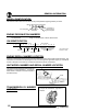
UNDERSTANDING SAFETY LABELS AND INSTRUCTIONS Throughout these instructions, important information is brought to your attention by the following symbols: The Safety Alert Symbol means ATTENTION! BECOME ALERT! YOUR SAFETY IS INVOLVED! DANGER Failure to follow DANGER instructions will result in severe injury or death to the operator, bystander or person inspecting or servicing the ATV.
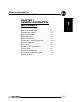
CHAPTER INDEX CHAPTER 1 GENERAL CHAPTER 2 MAINTENANCE CHAPTER 3 ENGINE CHAPTER 4 FUEL SYSTEM CHAPTER 5 BODY/SUSPENSION CHAPTER 6 PVT SYSTEM CHAPTER 7 FINAL DRIVE CHAPTER 8 TRANSMISSION CHAPTER 9 BRAKES CHAPTER 10 ELECTRICAL
GENERAL INFORMATION CHAPTER 1 GENERAL INFORMATION/ MAINTENANCE 2003 Model Identification . . . . . . . . . . . . . . . . . . Serial Number Location . . . . . . . . . . . . . . . . . . . 2003 Trailboss Model . . . . . . . . . . . . . . . . . . . . . Replacement Keys . . . . . . . . . . . . . . . . . . . . . . . Machine Dimensions . . . . . . . . . . . . . . . . . . . . . Specifications - 2003 Trail Boss 330 . . . . . . . . Publication Numbers . . . . . . . . . . . . . . . . . . . . . Paint Codes . . . . . .
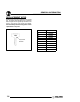
GENERAL INFORMATION MODEL IDENTIFICATION The machine model number must be used with any correspondence regarding warranty or service. Machine Model Number Identification A 03 CA 32 AA Year Designation Emissions & Model Option Basic Chassis Designation Engine Designation ENGINE DESIGNATION NUMBERS 32 ES32PFE10 . . . . . . . . . . . . Single, Air Cooled, SOHC 4 Stroke, Electric Start VIN IDENTIFICATION World Mfg.
GENERAL INFORMATION 2003 TRAILBOSS MODEL 2003 TRAILBOSS 330 1.
GENERAL INFORMATION REPLACEMENT KEYS Replacement keys can be made from the original key. To identify which series the key is, take the first two digits on the original key and refer to the chart to the right for the proper part number. Should both keys become lost, ignition switch replacement is required. Series # 31XX Key Series Number 1.
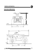
GENERAL INFORMATION MACHINE DIMENSIONS 46 in 117 cm FRONT 46 in 117 cm 75 in 191 cm 34 in 86 cm SIDE 49.5 in 126 cm 1.
GENERAL INFORMATION MODEL: . . . . . . . . . . 2003 TRAIL MODEL NUMBER: . A03CA32 ENGINE MODEL: . . ES32PFE10 BOSS 330 JETTING CHART CARBURETION Type . . . . . . . . . . . . . . . . Main Jet . . . . . . . . . . . . Pilot Jet . . . . . . . . . . . . . Jet Needle . . . . . . . . . . . Needle Jet . . . . . . . . . . . Pilot Screw . . . . . . . . . . Pilot Air Jet . . . . . . . . . . Valve Seat . . . . . . . . . . . Fuel Octane (R+M/2) . BST 34 Mikuni 122.5 42.5 4HB48--2 P-0M 2 Turns Out 160 1.
GENERAL INFORMATION MODEL: . . . . . . . . . . . . 2003 TRAIL MODEL NUMBER: . . . A03CA32 ENGINE MODEL: . . . . ES32PFE10 BOSS 330 ELECTRICAL Flywheel I.D. . . . . . . CDI Part Number . . . Alternator Output . . . Ignition Timing . . . . . Spark Plug / Gap . . . Lights: Head . . . . . . Tail . . . . . . . . Brake . . . . . . Indicator . . . Electric Start . . . . . . . Electronic Speedo . . FLUID None 4010697 210 watts 30°±2° BTDC@5000RPM NGK BKR6E / 0.0362 (0.9 mm) (2) Dual Beam 30/30 watts 8.
GENERAL INFORMATION PUBLICATION NUMBERS Year Model Model No. 2003 Trail Boss 330 A03CA32AA Owner’s Manual PN Parts Manual PN Parts Micro Fiche PN 9917862 9917863 9917492 NOTE: When ordering service parts be sure to use the correct parts manual. PAINT CODES PAINTED PART COLOR DESCRIPTION DITZLER NUMBER POLARIS NUMBER Springs Silver ---- P-385 Rims Bright White 2185 P-133 Rack(s) Black 9440 P-067 Frame Black 9440 P-067 FRAME COLOR - P067 Medium Gloss Black 9440 / 8520147.
GENERAL INFORMATION SAE TAP DRILL SIZES DECIMAL EQUIVALENTS Thread Size/Drill Size Thread Size/Drill Size #0-80 #1-64 #1-72 #2-56 #2-64 #3-48 #3-56 #4-40 #4-48 #5-40 #5-44 #6-32 #6-40 #8-32 #8-36 #10-24 #10-32 #12-24 #12-28 1/4-20 1/4-28 5/16-18 5/16-24 3/8-16 3/8-24 7/16-14 7/16-20 1/2-13 1/2-20 9/16-12 9/16-18 5/8-11 5/8-18 3/4-10 3/4-16 7/8-9 7/8-14 1-8 1-12 1 1/8-7 1 1/8-12 1 1/4-7 1 1/4-12 1 1/2-6 1 1/2-12 1 3/4-5 1 3/4-12 2-4 1/2 2-12 2 1/4-4 1/2 2 1/2-4 2 3/4-4 3-4 3/64 53 53 51 50 5/64 45 43
GENERAL INFORMATION CONVERSION TABLE Unit of Measure Multiplied by Converts to ft. lbs. x 12 = in. lbs. in. lbs. x .0833 = ft. lbs. ft. lbs. x 1.356 = Nm in. lbs. x .0115 = kg-m Nm x .7376 = ft.lbs. kg-m x 7.233 = ft. lbs. kg-m x 86.796 = in. lbs. kg-m x 10 = Nm in. x 25.4 =mm mm x .03937 = in. in. x 2.54 = cm mile (mi.) x 1.6 = km km x .6214 = mile (mi.) Ounces (oz) x 28.35 = Grams (g) Fluid Ounces (fl. oz.) x 29.
GENERAL INFORMATION GLOSSARY OF TERMS ABDC: After bottom dead center. ACV: Alternating current voltage. Alternator: Electrical generator producing voltage alternating current. ATDC: After top dead center. BBDC: Before bottom dead center. BDC: Bottom dead center. BTDC: Before top dead center. CC: Cubic centimeters. Center Distance: Distance between center of crankshaft and center of driven clutch shaft. Chain Pitch: Distance between chain link pins (No. 35 = 3/8² or 1 cm).
GENERAL INFORMATION NOTES 1.
MAINTENANCE CHAPTER 2 MAINTENANCE Periodic Maintenance Chart . . . . . . . . . . . . . . . Pre-Ride Inspection . . . . . . . . . . . . . . . . . . . . . . Recommended Maintenance Products . . . . . . Lubricant and Maintenance Quick Reference Special Tools . . . . . . . . . . . . . . . . . . . . . . . . . . . . Transmission Lubrication . . . . . . . . . . . . . . . . . . Transmission Linkage Adjustment . . . . . . . . . . Throttle Operation / Choke Adjustment . . . . . . Carburetor Adjustments . . . . . . .
MAINTENANCE PERIODIC MAINTENANCE CHART Inspection, adjustment and lubrication intervals of important components is listed in the following chart. Maintenance intervals are based upon average riding conditions and a vehicle speed of approximately 10 mph. Inspect, clean, lubricate, adjust or replace parts as necessary. NOTE: Inspection may reveal the need for replacement parts. Always use genuine Polaris parts.
MAINTENANCE PERIODIC MAINTENANCE CHART, CONT. CHASSIS Frequency (Whichever comes first) Item Hours Calendar Miles (Km) Remarks " General Lubrication 50 hrs 3 months 500 (800) Lubricate All Fittings, Pivots, Cables, Etc.
MAINTENANCE POLARIS LUBRICANTS,MAINTENANCE AND SERVICE PRODUCTS Part No. Description 2870584 Loctite 680-Retaining Compound (10 ml.) 2870587 Loctite 518 Gasket Eliminator / Flange Sealant (50 ml.) (10 Count) 2872113 Disk Brake Quiet (12 oz.) (12 Count) 2871326 Premium Carbon Clean (12 oz.) (12 Count) Fuel Stabilizer (16 oz.) (12 Count) Engine Lubricant 2870791 Fogging Oil (12 oz.
MAINTENANCE RECOMMENDED MAINTENANCE PRODUCTS - QUICK REFERENCE Item Type Notes See Pages Engine Oil Polaris Premium 4 Synthetic, 0W--40 Add to proper level on dipstick. Transmission Polaris Synthetic Gear Case Lubricant Refer to procedures outlined later in this chapter. Brake Fluid Polaris DOT 3 Brake Fluid Fill to indicated level inside reservoir. 2.17-2.18 2.8 2.23 MAINTENANCE QUICK REFERENCE Ill. # Item Lube Rec.
MAINTENANCE MAINTENANCE QUICK REFERENCE CONT’D 8. Rear Axle Bearings 7. Tie Rod End 9. Swing Arm Bushings 5. Front Wheel Bearings 6. Ball Joint Ill. # Item Lube Rec. Method Frequency* 5 Front Wheel Bearings Sealed; Replace Inspect and replace bearings if necessary Annually © 6 Ball Joint Polaris All Season Grease¢ Locate grease fitting on back side of struts and grease with grease gun. Semi-annually ¡ 7 Tie Rod Ends Polaris All Season Grease¢ Lift boot. Clean away dirt and grease.
MAINTENANCE SPECIAL TOOLS PART NUMBER TOOL DESCRIPTION CHAPTER TOOL USED IN PA--44689 Valve Clutch Adjuster 2 2870872 Shock Spanner Wrench 2, 5 8712100DX or 8712500 Tachometer 2,10 2200634 Valve Seat Reconditioning Kit 3 2870390 Piston Support Block 3 2870159 Flywheel Puller 3 2871293 Slotted Nut Socket 3 PV--43527 OIl Filter Wrench 3 2872314 Carburetor Float Adjustment Tool 4 2870975 Mity Vac Pressure Test Tool 4, 9 2870871 Ball Joint Replacement Tool 5 2870623 Shock
MAINTENANCE TRANSMISSION LUBRICATION The transmission lubricant level should be checked and changed in accordance with the maintenance schedule. G G G Be sure vehicle is level before proceeding. Check vent hose to be sure it is routed properly and unobstructed. Follow instructions on following pages to check / change transmission lubricant. TRANSMISSION SPECIFICATIONS Specified Lubricant: Polaris Premium Synthetic Gearcase Lubricant (PN 2871477) (Gallon) (PN 2871478) (12 oz.
MAINTENANCE TRANSMISSION GEARSHIFT LINKAGE ADJUSTMENT/ INSPECTION Linkage rod will rotate 1/8 -1/4 turn if rod ends are tightened properly. SHIFT LINKAGE ADJUSTMENT 1. Inspect shift linkage tie rod ends, clevis and pivot bushings and replace if worn or damaged. 2. Place gear selector in neutral. 3. Loosen rod end adjuster jam nuts (A) on both ends of linkage rod. NOTE: The jam nut closest to the knurled end is Left Hand thread.
MAINTENANCE THROTTLE OPERATION - ALL MODELS PILOT SCREW (IDLE MIXTURE) ADJUSTMENT Check for smooth throttle opening and closing in all handlebar positions. Throttle lever operation should be smooth and lever must return freely without binding. NOTE: These procedures are intended as reference only. Actual final settings may be different depending on the atmospheric conditions in your area. 1. 2. 3. 4. Place the gear selector in neutral. Set parking brake. Start the engine and let it idle.
MAINTENANCE IDLE SPEED ADJUSTMENT 1. Start engine and warm it up thoroughly. CV Carburetor 3. Tighten locknut and slide boots over cable adjuster until they touch at the middle point of the adjuster. 4. With engine running, turn the handlebars from full left to full right with transmission in neutral. Engine RPM should not change and the engine should not die. If either of these occur, return to the first step. THROTTLE OPERATION To remove the ETC cover: 1.
MAINTENANCE FUEL SYSTEM VENT LINES WARNING Gasoline is extremely flammable and explosive under certain conditions. G Always stop the engine and refuel outdoors or in a well ventilated area. Do not smoke or allow open flames or sparks in or near the area where refueling is performed or where gasoline is stored. Do not overfill the tank. Do not fill the tank neck. If you get gasoline in your eyes or if you swallow gasoline, seek medical attention immediately.
MAINTENANCE NOTE: The bowl drain screw is located on the bottom left side of the float bowl. 1. Turn fuel valve to the off position. 2. Place a clean container beneath the bowl drain spigot or bowl drain hose. RES Cylinder Compression Standard 70--90 PSI Cylinder Leakage Service Limit: 10 % (Inspect for cause if leakage exceeds 10%) ENGINE MOUNTS OFF Inspect rubber engine mounts for cracks or damage. ON Fuel Valve 3.
MAINTENANCE Maintenance--Free batteries are permanently sealed at the time of manufacture. The use of lead--calcium and AGM technology instead of lead--antimony allows the battery acid to be fully absorbed. For this reason, a Maintenance--Free battery case is dark and the cell caps are not removable, since there is no need to check electrolyte level. NEVER attempt to add electrolyte or water to a Maintenance--Free battery. Doing so will damage the case and shorten the life of the battery.
MAINTENANCE ENGINE-TO-FRAME GROUND Inspect engine-to-frame ground cable connection. Be sure it is clean and tight. Engine Ground Strap AIR FILTER/PRE-FILTER SERVICE It is recommended that the air filter and pre filter be replaced annually. When riding in extremely dusty conditions, replacement is required more often. The pre filter should be cleaned before each ride using the following procedure: 1. Lift up on the rear of the seat. 2. Pull the seat back and free of the tabs.
MAINTENANCE NOTE: Apply a small amount of general purpose grease to the sealing edges of the filter before reinstalling. Filter Clamp Sediment Tube NOTE: The sediment tube will require more frequent service if the vehicle is operated in wet conditions or at high throttle openings for extended periods. ILL.1 Proper Filter Placement Main Filter 1. Remove drain plug from end of sediment tube. 2. Drain tube. 3. Reinstall drain plug.
MAINTENANCE G G G G sealed properly, water may enter the recoil housing and damage components. Water will enter the recoil housing if the starter handle is disengaged from the rope guide when under water. After travelling in wet areas, the recoil housing and starter should always be drained completely by removing the recoil. Do not open the crankcase drain unless the engine has ingested water. Some engine oil will be lost if crankcase drain is opened.
MAINTENANCE OIL AND FILTER CHANGE 1. Place vehicle on a level surface. 2. Clean area around drain plug at bottom of oil pan. 3. Run engine two to three minutes until warm. Stop engine. 4. Place a drain pan beneath oil pan and remove drain plug from under the crankcase. CAUTION: Oil may be hot. Do not allow hot oil to come into contact with skin as serious burns may result. 5. Allow oil to drain completely.
MAINTENANCE VALVE CLEARANCE Inspect and adjust valve clearance while the engine is cold and the piston positioned at Top Dead Center (TDC) on compression stroke. 1. Remove the seat. 2. Remove body panels and fuel tank as necessary to gain access to valve cover. 3. Remove the spark plug high tension lead and remove the spark plug. CAUTION: Place a clean shop towel into the spark plug cavity to prevent dirt from entering. 4. Remove plastic valve plugs. 330 Valve Plugs INTAKE VALVE CLEARANCE ADJUSTMENT 1.
MAINTENANCE 1. Insert .006² feeler gauge between end of exhaust valve stem and adjuster screw. EXHAUST VALVE CLEARANCE: 0.006±0.0008I (0.15±0.02 mm) BTDC on compression 2. Loosen locknut and turn adjuster screw until there is a slight drag on feeler gauge. 3. When clearance is correct, hold adjuster screw and tighten locknut securely 4. Re-check the valve clearance. 5. Repeat adjustment procedure if necessary until clearance is correct with locknut secured. 6.
MAINTENANCE G G If abnormal movement is detected, inspect the hub and wheel assembly to determine the cause. Refer to the Body/Steering or Final Drive chapter for more information. CAMBER AND CASTER The camber and caster are non-adjustable. WHEEL ALIGNMENT METHOD: STRAIGHTEDGE OR STRING Be sure to keep handlebars centered. See notes below. NOTE: String should just touch side surface of rear tire on each side of machine. Measure from string to rim at front and rear of rim.
MAINTENANCE TOE ALIGNMENT ADJUSTMENT EXHAUST CLEANING If toe alignment is incorrect, measure the distance between vehicle center and each wheel. This will tell you which tie rod needs adjusting. NOTE: Be sure handlebars are straight ahead before determining which tie rod(s) need adjustment. CAUTION: During tie rod adjustment it is very important that the following precautions be taken when tightening tie rod end jam nuts. If the rod end is positioned incorrectly it will not pivot, and may break.
MAINTENANCE 5. If particles are still suspected to be in the muffler, drive the machine onto the incline so the front of the machine is one foot higher than the rear. Set the hand brake and block the wheels. Make sure the machine is in neutral and repeat Steps 2 and 3. SEE PREVIOUS WARNING 6. Repeat Steps 2 through 5 until no more particles are expelled when the engine is revved. 7. Stop the engine and allow the arrestor to cool. 8. Reinstall the clean out plugs. BRAKE PAD INSPECTION 3/64² (.
MAINTENANCE If less than one inch, two things must be examined: Free Play: Free play of the brake pedal should be 1/8 - 1/4 inch (3.2 - 6.35 mm). If free play is excessive, inspect pedal, linkage, and master cylinder for wear or damage and replace any parts as needed. Bleeding: If free play is correct and brake pedal travel is still excessive, air may be trapped somewhere in the system. Bleed the hydraulic auxiliary brake system in a conventional manner, following the procedure outlined in Brake Chapter 9.
MAINTENANCE After inspection, again slowly move the ATV forward until all the chain slack is on the top side of the chain and inspect the deflection. Repeat this procedure several times to check different spots on the chain. The chain is correctly adjusted when the tightest portion of the chain itself has approximately 3/8 in., (10 mm) of deflection. It’s a common characteristic of any chain to have one or more tight spots in the chain.
MAINTENANCE CAUTION: DO NOT OVER-TIGHTEN ECCENTRIC CLAMP BOLTS. PRE-MATURE BEARING FAILURE MAY RESULT. Loosen Eccentric Clamp Without Hitch Tighten Torque the nut WITHOUT TRAILER HITCH - 30 ft. lbs. (41 Nm) 7. Tighten caliper mounting bracket bolts 10-12 ft. lbs. (14 - 17 Nm) Caliper Mount Bracket SUSPENSION SPRING PRELOAD ADJUSTMENT Operator weight and vehicle loading affect suspensionspringpreloadrequirements. Adjustas necessary to avoid bottoming of the shocks.
MAINTENANCE CONTROLS 4. Remove the wheel nuts and remove the wheel. Check controls for proper operation, positioning and adjustment. Tapered nuts - install with tapered side against wheel G Brake control and switch must be positioned to allow brake lever to travel throughout entire range without contacting switch body. WHEELS Inspect all wheels for runout or damage. Check wheel nuts and ensure they are tight. Do not over tighten the wheel nuts.
MAINTENANCE TIRE PRESSURE Tire Pressure Inspection (PSI - Cold) Front Rear 4 3 TIRE INSPECTION WARNING Operating an ATV with worn tires will increase the possibility of the vehicle skidding and possible loss of control. Worn tires can cause an accident. Always replace tires when the tread depth measures 1/8² (.3 cm) or less. CAUTION: G G G G Maintain proper tire pressure. Refer to the warning tire pressure decal applied to the vehicle. Improper tire inflation may affect ATV maneuverability.
ENGINE CHAPTER 3 ENGINE Engine Service Data . . . . . . . . . . . . . . . . . . . . . . . . . Special Tools and Torque Specifications . . . . . . . . Torque Patterns . . . . . . . . . . . . . . . . . . . . . . . . . . . . . Piston Identification . . . . . . . . . . . . . . . . . . . . . . . . . . Engine Removal . . . . . . . . . . . . . . . . . . . . . . . . . . . . Engine Installation Notes . . . . . . . . . . . . . . . . . . . . . Cylinder Honing . . . . . . . . . . . . . . . . . . . . . . . . . . . . .
ENGINE ES32PFE10 ENGINE SERVICE DATA Cylinder Head / Valve Rocker Arm Camshaft ES32PFE10 Rocker arm ID Rocker shaft OD Rocker shaft Oil Clearance Cam lobe height g In Ex Camshaft jjournal OD Camshaft jjournal bore ID Camshaft Oil clearance Cylinder y Head Valve Seat Surface warpage limit Standard height Contacting g width In Ex Valve Guide Valve Inner diameter Protrusion above head Margin g thickness Valve Stem diameter Stem oil clearance Overall length g Valve Spring p g Free length g Squaren
ENGINE ES32PFE10 ENGINE SERVICE DATA Cylinder Piston Piston Pin Cylinder / Piston / Connecting Rod Surface warpage limit (mating with cylinder head) Cylinder bore Std Taper limit Out of round limit Piston clearance Std Limit Boring limit Outer diameter Std .0098² (.25 mm) OS .0197² (.
ENGINE SPECIAL TOOLS Oil Line Fitting PART NUMBER TOOL DESCRIPTION 2200634 Valve Seat Reconditioning Kit Piston Support Block 2870390 2870159 Flywheel Puller 2871293 Slotted Nut Socket PV--43527 Oil Filter Wrench TORQUE SPECIFICATIONS ENGINE TORQUE SPECIFICATIONS Fastener Size 330 ES32PFE10 Ft. Lbs. (Nm) Camshaft Chain Tensioner Lever 6mm 5-6.5 (7-9 Nm) Camshaft Chain Tensioner 6mm 5-6.
ENGINE PISTON IDENTIFICATION The following components removal for service: The piston may have an identification mark or the piston may not have an identification mark for piston placement. If the piston has an identification mark, follow the directions for piston placement below. If the piston does not have an identification mark, the direction for placement of the piston does not matter. Note the directional and identification marks when viewing the pistons from the top.
ENGINE ENGINE INSTALLATION NOTES After the engine is installed in the frame, review this checklist and perform all steps that apply. General Items G Install previously removed components using new gaskets, seals, and fasteners where applicable. G Perform regular checks on fluid levels, controls, and all important areas on the vehicle as outlined in the daily pre-ride inspection checklist (refer to Chapter 2). PVT System G Adjust center distance of drive and driven clutch.
ENGINE If cylinder wear or damage is excessive, it will be necessary to replace the cylinder. Hone only enough to deglaze the outer layer of the cylinder bore. rough or sharp edges. Apply a slight chamfer to all ports to remove sharp edges or burrs, paying particular attention to the corners of the intake and exhaust ports.
ENGINE 3. Start engine and allow it to reach operating temperature while monitoring gauge indicator. NOTE: Use Polaris Premium 0--40W Synthetic Engine Lubricant (PN 2871281). ES32PF10 Oil Pressure at 3000 RPM (Engine Hot): Standard: 71-99 PSI Minimum: 20 PSI at idle OIL COOLER ASSEMBLY Top Bracket To Engine Fan Motor Screws Shroud Thermistor Inlet Hose Oil Cooler Hose Clamps Lower Bracket Rubber Mounts U--Clips 3.
ENGINE OIL FLOW DIAGRAM - ES32PF Small End Bearing Cylinder Sleeve Chain Room Piston Rocker Arm / Rocker Shaft / Sprocket / Chain Oil Jet (Fixed) Connecting Rod Main Bearing Cam Lobe Large End Bearing Indirect Lubrication Cam Shaft Journal Cam Shaft Journal Through Front Right Cylinder Head Bolt Passage Oil Passage In Cylinder Crank Pin Crankcase Oil Passage Oil Hoses Crankcase Oil Passage Crankshaft In Out Bypass Oil Filter Pressure Relief Engine Sump Oil Pickup Screen Oil Pump Crankcas
ENGINE ES32PFE ENGINE EXPLODED VIEW Crankcase ES32PF Crankshaft and Piston 3.
ENGINE ENGINE REMOVAL REFER TO PAGE 3.5 - 3.6 FOR ENGINE REMOVAL / INSTALLATION NOTES. CAM CHAIN TENSIONER REMOVAL 5. Remove cam chain tensioner plug, sealing washer, spring and pin. CAUTION: The plug is under spring tension. Maintain inward pressure while removing. 6. Remove the two 6x25 mm cam chain tensioner flange bolts. 7. Tap lightly on tensioner body with a soft face hammer and remove tensioner. 1. Remove ignition timing inspection plug from recoil housing.
ENGINE 4. Measure free length of tensioner spring. Replace spring if excessively worn. 4. Remove cylinder block plug using a 14 mm hex head wrench. Cylinder block plug Tensioner Spring Free Length: 2.06² (5.23 cm) Std. 1.92² (4.88 cm) Limit 5. Measure O.D. of rocker shaft. Inspect it for wear or damage. Compare to specifications. 5. Replace entire tensioner assembly if any part is worn or damaged. ROCKER ARM/SHAFT INSPECTION 1. Remove rocker cover. 2.
ENGINE CAMSHAFT REMOVAL 1. Remove cam shaft end plug (A). A Rocker Arm & Support I.D.: .8669-.8678I (22.020-22.041 mm) 2. Remove camshaft sprocket flange bolt and washer. 7. Measure I.D. of both rocker arm shaft support areas and visually inspect surface. Compare to specifications. 3. Place a clean shop towel in the area below cam chain sprocket. Rocker Shaft Oil Clearance: Std: .0008-.0021I (.020-.054 mm) Limit: .0039I (.10 mm) 8.
ENGINE CAMSHAFT REMOVAL CONT’D 6. Inspect cam sprocket teeth for wear or damage. Replace if necessary. Lobe Inspect for Areas of Tooth Wear or Damage 2. Remove release lever shaft and return spring (spacer). 3. Inspect shaft for wear or galling. 4. Inspect lobe on end of release lever shaft for wear and replace if necessary. 7. Remove camshaft. Return spring (spacer) AUTOMATIC COMPRESSION RELEASE INSTALLATION 1. Slide spring onto shaft. 2. Apply engine oil to release lever shaft.
ENGINE 2. Thoroughly clean the cam shaft, making sure the oil feed holes are not obstructed. 3. Measure height of each cam lobe using a micrometer. Compare to specifications. 4. Measure camshaft journal outside diameter (O.D.) CYLINDER HEAD REMOVAL 1. Loosen each of the four cylinder head bolts evenly 1/8 turn each time in a cross pattern until loose. Journal O.D. A Journal Camshaft Journal O.D.: Mag & PTO End: 1.4935-1.4941I (37.935-37.950 mm) 2.
ENGINE CYLINDER HEAD WARPAGE 2. Remove spring retainer and spring. 1. Lay a straight edge across the surface of the cylinder. head at several different points and measure warpage by inserting a feeler gauge between the straight edge and the cylinder head surface. If warpage exceeds the service limit, replace the cylinder head. A NOTE: The valve springs should be positioned with the tightly wound coils against the cylinder head on progressively wound springs (A). Cylinder Head Warpage Limit: .002” (.
ENGINE 5. Remove valve seals. CAUTION: Replace seals whenever the cylinder head is disassembled. Hardened, cracked or worn valve seals will cause excessive oil consumption and carbon buildup. A B VALVE INSPECTION 1. Remove all carbon from valve with a soft wire wheel. 2. Check valve face for runout, pitting, and burnt spots. To check for bent valve stems, mount valve in a drill or use “V” blocks and a dial indicator. 4. Inspect split keeper groove for wear or flaring of the keeper seat area (B).
ENGINE VALVE SEAT RECONDITIONING Valve Seat Inspection Inspect valve seat in cylinder head for pitting, burnt spots, roughness, and uneven surface. If any of the above conditions exist, the valve seat must be reconditioned. See Valve Seat Reconditioning, Page 3.19--3.21. If the valve seat is cracked the cylinder head must be replaced. 7. Subtract valve stem measurement to obtain stem to guide clearance. NOTE: Be sure to measure each guide and valve combination individually. 8.
ENGINE 4. Follow the manufacturers instructions provided with the valve seat cutters in the Valve Seat Reconditioning Kit (PN 2200634). Abrasive stone seat reconditioning equipment can also be used. Keep valves in order with their respective seat. NOTE: Valve seat width and point of contact on the valve face is very important for proper sealing. The valve must contact the valve seat over the entire circumference of the seat, and the seat must be the proper width all the way around.
ENGINE VALVE SEAT RECONDITIONING CONT’D 3. Place 46° cutter on the pilot and make a light cut. 6. Insert valve into guide and tap valve lightly into place a few times. 7. Remove valve and check where the Prussian Bluet or black marker indicates seat contact on the valve face. The valve seat should contact the middle of the valve face or slightly above, and must be the proper width (A). (B) (A) 4. Inspect the cut area of the seat.
ENGINE NOTE: When using an interference angle, the seat contact point on the valve will be very narrow, and is a normal condition. Look for an even and continuous contact point on the black marker, all the way around the valve face. 12. Clean cylinder head, valves, and camshaft oil supply passage (A) thoroughly. A Seat Width Valve Seat Width: Intake Std: .039I (1.0 mm) Limit: .055I (1.4 mm) Exhaust Std: .059I (1.4 mm) Limit: .071I (1.8 mm) 13.
ENGINE CYLINDER HEAD ASSEMBLY CONT’D 5. Dip valve spring and retainer in clean engine oil and install spring with closely spaced coils toward the cylinder head. ENGINE BOTTOM END DISASSEMBLY Cylinder Removal Follow engine disassembly procedures to remove valve cover, camshaft and rocker arms, and cylinder head. Closely spaced coils toward cylinder head 1. Remove cam chain guide at front of cylinder. 2. Remove the two 6 mm cylinder base bolts. 6.
ENGINE PISTON REMOVAL 1. Remove circlip. Note that opening for circlip access is on the intake side. 5. Remove the top rail first followed by the bottom rail. 6. Remove the expander. CYLINDER INSPECTION 1. Remove all gasket material from the cylinder sealing surfaces. 2. Inspect the top of the cylinder for warpage using a straight edge and feeler gauge. 2. Remove piston circlip and push piston pin out of piston. If necessary, heat the crown of the piston slightly with a propane torch.
ENGINE CYLINDER INSPECTION CONT’D 5. Record measurements. If cylinder is tapered or out of round beyond .002, the cylinder must be re-bored oversize, or replaced. 3. Measure piston pin bore. Cylinder Taper Limit: .002 Max. Cylinder Out of Round Limit: .002 Max. Standard Bore Size: 3.0906-3.0913I (78.50-78.520 mm) PISTON INSPECTION 1. Measure piston outside diameter at a point 5 mm up from the bottom of the piston at a right angle to the direction of the piston pin. Piston Pin Bore: .7095-.7097I (18.
ENGINE 5. Measure connecting rod small end ID. PISTON RING INSTALLED GAP 1. Place each piston ring inside cylinder using piston to push ring squarely into place as shown. Piston ring end gap installed Feeler Gauge Cylinder 25-50mm Connecting Rod Small End I.D. Piston Ring .7095-.7101I (18.007-18.023 mm) 6. Measure piston ring to groove clearance by placing the ring in the ring land and measuring with a thickness gauge. Replace piston and rings if ring-to-groove clearance exceeds service limits.
ENGINE STARTER DRIVE REMOVAL/INSPECTION 1. Remove recoil housing bolts and remove housing. Starter Drive Bushing Clearance: Std: .0015²-.004² (.038-.102 mm) Service Limit: 008² (.203 mm) 6. Inspect gear teeth on starter drive. Replace starter drive if gear teeth are cracked, worn, or broken. FLYWHEEL/STATOR REMOVAL/INSPECTION 1. Remove flywheel nut and washer. 2. Remove starter drive assembly. Note the thrust washer located at the rear of the drive mechanism. 3.