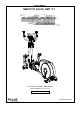
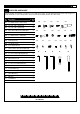
USER’S MANUAL SMOOTH AGILE DMT X1 USER WEIGHT LIMITATION: 350lbs(160kgs).
SMOOTH AGILE DMT X1 PREASSEMBLY For future service or related questions: Please staple your receipt and/or write in the name and phone number of the retail store where you purchased your Smooth Fitness AGILE DMT X1. Name: ______________________________ Phone Number: ___________________ Receipt: ______________________ Open the boxes: You are now ready to open the boxes of your new equipment. Make sure to inventory all of the parts that are included in the boxes.
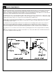
www.smoothfitness.com 3 POWER REQUIREMENTS Power Requirements: IMPROPER CONNECTION OF THE EQUIPMENT GROUNDING CONNECTOR CAN RESULT IN THE RISK OF AN ELECTRIC SHOCK. CHECK WITH A QUALIFIED ELECTRICIAN OR SERVICE MAN IF YOU ARE IN DOUBT AS TO WHETHER THE PRODUCT IS PROPERLY GROUNDED. DO NOT MODIFY THE PLUG PROVIDED WITH THE PRODUCT, IF IT WILL NOT FIT THE OUTLET; HAVE A PROPER OUTLET INSTALLED BY A QUALIFIED ELECTRICIAN.
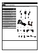
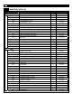
SMOOTH AGILE DMT X1 SUPPLIED COMPONENTS This list identifies the major components you will use to assemble this product. No. Description Qty.
www.smoothfitness.com 5 SUPPLIED HARDWARE This list identifies the hardware you will use to assemble the product. To help distinguish between the various types of screws and bolts, use the scale below to measure them and compare them to the sizes listed. No. Description Qty.
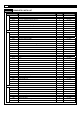
SMOOTH AGILE DMT X1 COMPLETE PARTS LIST Item No. Description Qty. Part No.
www.smoothfitness.com COMPLETE PARTS LIST Item No. Description Qty. Part No.
SMOOTH AGILE DMT X1 COMPLETE PARTS LIST Item No. Description Qty. Part No. 331 Wheel Cap 112 x 41.5mm 2 X1-331 332 Wheel Cap 46 x 12mm 2 X1-332 333 Wheel 140 x 51.
www.smoothfitness.com COMPLETE PARTS LIST Item No. 429 430 431 432 433 435 436 437 438 439 441 442 443 444 445 446 447 448 449 450 451 452 453 454 455 456 457 458 459 460 461 462 467 468 469 500 501 502 503 504 505 506 507 508 509 510 Description Qty. Part No. M10 x20mm Bolt 10 x 16 x 2mm Spring Washer 10 x 30 x T3.0 Washer M4 Nylon Nut M10 Nylon Nut 16 x 25 x T3.0 Washer M10 x 40mm Allen Head Bolt Thread:10mm M6 x 12mm Screw 17 x 22 x T1.
SMOOTH AGILE DMT X1 COMPLETE PARTS LIST Item No. 511 513 514 515 516 517 520 521 600 601 602 603 604 605 606 607 608 609 610 611 612 613 614 615 616 617 618 619 620 621 622 623 624 625 626 627 628 700 701 702 703 704 705 706 707 708 Description Qty. Part No. M10 x 40mm Allen Head CAP Bolt 8 x 27 x 2mm Washer 8 x 14 x T2.0mm Spring Washer M8 x 20mm Allen Head Bolt M5 x 6mm Screw 10 x 16 x T2.0mm Spring Washer 8 x 27 x 1mm Plastic Washer 20.7 x 29.1 x 0.
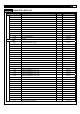
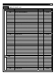
www.smoothfitness.com PARTS DIAGRAM MOST OF THE PARTS SHOWN HERE HAVE BEEN PRE-ASSEMBLED.
SMOOTH AGILE DMT X1 PARTS DIAGRAM MOST OF THE PARTS SHOWN HERE HAVE BEEN PRE-ASSEMBLED.
www.smoothfitness.com 13 PARTS DIAGRAM MOST OF THE PARTS SHOWN HERE HAVE BEEN PRE-ASSEMBLED. 320 415 414 321.
SMOOTH AGILE DMT X1 PARTS DIAGRAM MOST OF THE PARTS SHOWN HERE HAVE BEEN PRE-ASSEMBLED.
www.smoothfitness.com 15 PARTS DIAGRAM MOST OF THE PARTS SHOWN HERE HAVE BEEN PRE-ASSEMBLED.
SMOOTH AGILE DMT X1 PARTS DIAGRAM MOST OF THE PARTS SHOWN HERE HAVE BEEN PRE-ASSEMBLED.
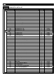
www.smoothfitness.com ASSEMBLY MOST OF THE PARTS SHOWN HERE HAVE BEEN PRE-ASSEMBLED.
SMOOTH AGILE DMT X1 ASSEMBLY STEP 1: Connect the Main Frame to Incline Frame (A) Place Styrofoam block under Main Frame tube to provide clearance to position Incline Frame (109) for assembly. Remove the Blue film before you assemble the Incline Frame. (B) Hold the Incline Frame Holder – Front (708) to the Incline Frame (109), secure using M10 x 40mm Allen Head CAP Bolts (511), 10 x 16 x T2.0mm Spring Washer on the Incline Frame Holder by 8mm Allen Key (C).
www.smoothfitness.com ASSEMBLY STEP 2: Connect the Incline Transmission Tube (A) Rotate the Incline Frame (109) to align the bolt holes with the mating bolt holes in the Incline Transmission Tube-Front (110). 507 X1 (B) Assemble the Incline Transmission Tube-Front (110) to the Incline Frame (109) with M10 x 56mm Allen Head Bolt (507), M10 Nylon Nut (508), and by 8mm Allen Key (C) and Wrench (D). 508 X1 (C) Tight the M10 x40mm Allen Head CAP Bolt (511) by 8mm Allen Key.
SMOOTH AGILE DMT X1 ASSEMBLY STEP 3: Assemble the Console Support Tube (A) Assemble the Console Support Tube (101) to the Main Frame and secure using four M8 x 16mm Allen Head CAP Bolts (504) by 6mm Allen Key (B) 504 X4 (B) Connect the 8Pin Power Wire – Middle (602) to 8Pin Power Wire – Lower (603).
www.smoothfitness.com ASSEMBLY STEP 4: Assemble the Handlebar (A) Place the Nylon Bushing (706) into the Console Support Tube (101). NOTE: THE EMBOSS SHAPE OF NYLON BUSHING MUST OUTWARD TO HANDLEBAR. (B) Assemble the Handlebar – Right (103) to the Console Support Tube (101) by M8 x 20mm Allen Head Bolt (515), 8 x 27 x 1mm Plastic Washer (520), 8 x 14 x T2.0mm Spring Washer (514) and 8 x 27 x 2mm Washer (513) and then press the Action Handlebar Cap into the Handlebar.
SMOOTH AGILE DMT X1 ASSEMBLY STEP 5: Assemble the Undercarriage Cover (A) Lift the Pedal Arm and assemble the Undercarriage Cover – Left (704) to the Main Frame (112), and secure using two 4 x 12mm Screw – Flat Point (506) and two 4.5 x 15mm Screws (510). 506 X4 510 X4 509 X3 (B) Repeat above the procedure to assemble the right side. (C) Secure using the 4 x 19mm Screw (509) to integrate the right and left cover.
www.smoothfitness.com ASSEMBLY STEP 6: Assemble the Incline Frame Cover (A) Assemble the Incline Frame Cover (703) to the Incline Frame and secure using two 4.5 x 15mm Screws (510).
SMOOTH AGILE DMT X1 ASSEMBLY STEP 7: Connect the Pedal Arm to the Pedal Swing Arm (A) Slide the 20 x 78 – M14 x 35mm Bolt (505) through the 20.7 x 29.1 x 0.3mm Wave Washer (521), Pedal Arm – Right (107), and Pedal Swing Arm (108) then secure by 8mm Allen Key (C) 505 X2 (B) Press the Pedal Arm Front Pivot Cover (702) into the ends of the Pedal Arm – Right (107) 521 X2 (C) Repeat the above procedure to assemble the left side.
www.smoothfitness.com ASSEMBLY STEP 8: Connect the Moving Linkage (A) Connect the Action Handlebar – Right (103) to the Moving Linkage – Right (105) and secure using the 15 x 22 – M8 x 10mm Bolt (502)and 15 x 26 – M8 x 15mm Bolt (503) by 8mm Allen Key (C). (B) Repeat the above procedure to assemble the left side.
SMOOTH AGILE DMT X1 ASSEMBLY STEP 9: Assemble the Action Handlebar Lower Cover (A) Assemble the Action Handlebar Lower Cover (701) to the Action Handlebar – Right (103) and secure using the 4 x 12mm Screw – Cone Point (501) (B) Repeat the above procedure to assemble the left side.
www.smoothfitness.com ASSEMBLY STEP 10: Tighten Set Screws (A) Secure the M5 x 6mmBolt (516) to the Pedal Swing Arm (108) using the 2.
SMOOTH AGILE DMT X1 LEVEL ADJUSTMENT LEVEL ADJUSTMENT: To adjust the levelers follow these instructions: You will need someone to help you with this procedure, as you will need to tip, the AGILE Dynamic Motion Trainer while adjusting the levelers Tip the AGILE Dynamic Motion Trainer to the left/right. You will then see the LEVEL ADJUSTERS. These will need to be screwed either in or out to level the trainer. Repeat for the other side.
www.smoothfitness.com 29 LITE-TOUCH CONTROL OPERATION LITE-TOUCH CONTROL: The Intensity Level and Motion Level can be controlled using the Lite-Touch controls on the hand grips of the action handlebars. As the illustration indicates, the right Lite-Touch Controller controls the Motion Level and the left Lite-Touch Controller controls the Intensity Level. You can see the corresponding readouts on the console follow this same orientation.
SMOOTH AGILE DMT X1 TRANSPORT INSTRUCTION TRANSPORT INSTRUCTIONS: To transport your AGILE Dynamic Motion Trainer simply lift the back end and roll it away to the desired location, as shown.
www.smoothfitness.com MUSCLE CHART Targeted muscle groups: The exercise routine that is performed on this product will develop primarily lower body muscle groups. These muscle groups are shown in gray color on the chart below.
SMOOTH AGILE TRAINER STRETCHING ROUTINE Warm up and cool down: A successful exercise program consists of a warm-up, aerobic exercise, and a cool-down. Do the entire program at least two and preferably three times a week, resting for a day between workouts. After several months, you can increase your workouts to four or five times per week. Warming up is an important part of your workout, and should begin every session.
www.smoothfitness.
SMOOTH AGILE TRAINER COMPUTER OPERATION DISPLAY FUNCTIONS: INTENSITY LEVEL DISPLAY: Displays intensity level from 1 to 16. MOTION LEVEL DISPLAY: Displays motion level from 1 to 12. 8 X 16 DOT MATRIX INTENSITY LEVEL PROFILE DISPLAY: Displays all operating instructions prior to the workout and displays intensity level profile during the workout. USER DATA: Displays and store user data from U1 to U9.
www.smoothfitness.com 35 COMPUTER OPERATION PROGRAM OPERATION INSTRUCTION: At POWER ON status, press STOP/ENTER button to enter preset PROGRAM MODE and to set user parameters. SET UP USER CODE: At first, the LCD will show a blinking U1, and will also display only factory default setting values for user HEIGHT, WEIGHT, AGE and GENDER. Press the INTENSITY UP/DOWN buttons to choose the User ID from U1 to U9 and press the STOP/ENTER buttons to assign the user ID shown.
SMOOTH AGILE TRAINER COMPUTER OPERATION PROGRAM 5 – INTERVAL INTENSITY After enter this program, the TIME display shows “L1”. This indicates the intensity level for the intervals. Use the INTENSITY UP/DOWN buttons to change the intensity then press STOP/ENTER button to enter to confirm. TIME display shows factory default setting “32:00”. Press INTENSITY UP/DOWN button to adjust the target time and press STOP/ENTER to confirm. Press START button to start the INTERVAL INTENSITY program.
www.smoothfitness.com 37 COMPUTER OPERATION PROGRAM 7 – ENDURANCE After enter this program, the TIME display shows “L1”. Press INTENSITY UP/DOWN button to adjust the workout level and press STOP/ENTER to confirm. TIME display shows factory default setting “32:00”. Press INTENSITY UP/DOWN button to adjust the target time and press STOP/ENTER to confirm. Press START button to start the ENDURANCE program. Time counts down to 0, Distance and Calories count up.
SMOOTH AGILE TRAINER COMPUTER OPERATION PROGRAM 8 – WATTS CONTROL The function of Watts Control program is to allow the user to set a desired workout load (watts). The user’s workout load is controlled automatically by increasing or decreasing the resistance as the user changes their stride cadence (RPM). The intensity will be reduced when user increases RPM and the intensity will be increased when the user decreases the RPM.
www.smoothfitness.com 39 COMPUTER OPERATION P10: CUSTOMER COURSE When the user selects P10 CUSTOM program and press STOP/ENTER button, C1 will display and flash on the LCD. The program can allow each user to create 5 individual custom programs and store the settings for repeated workouts. To select the program from C1 to C5, press the INTENSITY UP/DOWN button. Press STOP/ENTER button and hold it for 3 seconds to confirm the selection and then continues to set up.
SMOOTH AGILE TRAINER COMPUTER OPERATION Heart Rate diagram 205 195 Heartrate (beats per min) 185 175 Adv an 165 155 ce P erfor m ance Aero bic 145 135 F at B urnin g 125 115 Warm U 105 p / C oo l Dow n 95 90 20 25 30 35 40 45 50 55 60 65 70 Age (years) You can calculate the target-heartrate for your training as follows: Maximum heartrate = 220 minus age For the different trainingtargets you should train with the following percentage of your maximum heartrate: Health/Fat Burni
www.smoothfitness.com 41 WARRANTY LIMITED HOME USE WARRANTY – SMOOTH FITNESS Ellipticals and DMTs Warranty Warranty Coverage: EVO Fitness and Smooth Fitness, Inc. ("Smooth Fitness") warrants to the original owner that each new product to be free from defects in workmanship and material, under normal use and conditions.
SMOOTH AGILE TRAINER Smooth thFitness 780 5 Ave King of Prussia, PA 19406 Toll Free Customer Service: 1.888.800.1167 Website: www.smoothfitness.