Users Guide: iMFD User Guide DM-100 OBDII Touch OLED Gauge DM-100 OBDII Touch User Guide (V2.0) May 16, 2013 A Silicon Valley California Company DM-100 OBDII Touch Universal OLED Multi-Gauge User Guide This Product has Patents Pending Designed by PLX Devices Inc. in Sunnyvale, CA © PLX Devices 2013 All Rights Reserved Version 2.0 May 16, 2013 www.plxdevices.
Users Guide: iMFD User Guide Table of Contents 1 INTRODUCTION 5 1.1 Patents ................................................................................................................................................... 5 1.2 Warnings ............................................................................................................................................... 5 1.3 Key Features .....................................................................................................
Users Guide: iMFD User Guide 4.2 Digital Gauges (Numeric) ......................................................................................................... 14 4.3 Plot Gauges ........................................................................................................................................ 14 4.4 Peak and Hold .................................................................................................................................. 14 4.5 Two Parameter Gauges ....
Users Guide: iMFD User Guide 9 REVISION HISTORY 23 4 Version 2.0 May 16, 2013 www.plxdevices.
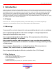
Users Guide: iMFD User Guide 1 Introduction Thank you for purchasing the DM-100 OBDII Touch, the world’s most versatile gauge with plug and play OBDII capabilities. The DM-100 OBDII Touch enables you to take advantage of the latest and cutting edge technologies which are only employed in high end consumer electronics today. The Organic LED display offers excellent color contrast and unsurpassed viewing angles that far exceed that of traditional LCD displays.
Users Guide: iMFD User Guide 8) 9) 10) 11) 12) 13) 14) Peak and hold (high and low) Intelligent warning (4 parameter comparison) Custom gauge design 4 point capacitive sense touch screen Custom wallpaper upload Automatic sensor detection Extruded aluminum construction 1.4 Package Contents 1) 2) 3) 4) 5) 6) DM-100 OBDII Touch Control Module HDD-100 52mm OLED Display with touch screen Power wire with 2.1mm connector and cigarette adapter 1ft Serial Cable 6ft USB Cable Users Guide 1.
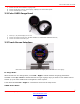
Users Guide: iMFD User Guide 7) 8) 9) Connect to touch screen interface on gauge head Connect to USB port on PC for custom gauge, wallpaper, and sensor table upload Connect to OBDII port in vehicle 2.2 Color OLED Gauge Head 1) 2) 3) 52mm (2 1/16”) OLED Display for DM-100 Connect to Control Box HDD port. (DO NOT CONNECT TO COMPUTER’s MONITOR OUTPUT!) Connect to Control Box Remote port. 2.
Users Guide: iMFD User Guide While the DM-100 is in Sensor Mode, touch Left – Right to switch between pages. Please refer to section (2.4) for more details how to navigate the menu system. Setup Mode: While in the DM-100 is in Setup Mode, follow the arrows on the screen to navigate and setup your gauge. At any time, touch and hold both Left – Right for 3 seconds to enter and exit the setup menu. 2.4 Navigating the Menus 2.4.1 Gauges 8 Version 2.0 May 16, 2013 www.plxdevices.
Users Guide: iMFD User Guide 2.4.2 OBDII Parameters 3 Hardware 3.1 Connecting Power Option 1: Using the Cigarette Lighter Power This option is ideal if your cigarette lighter power is only ON when your ignition key is turned. In some vehicles, your cigarette lighter power is always ON. Leaving your DM-100 OBDII unit always powered on will drain your vehicle’s battery quickly. If this is the case for your vehicle, we recommend option 2. Plug the 2.
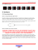
Users Guide: iMFD User Guide The unit is working properly when the OLED screen turns on within 10 seconds. If your gauge does not turn on, check your power connections and gauge connections. 3.2 iMFD Daisy Chain The iMFD architecture allows you to connect up to 16 Display Modules and 16 Sensors in a daisy chain format. Please keep in mind that the DM-100 Touch has 4 SMs built-in. The 4 built-in SMs can be programmed up to 26 different combinations. See section (3.3).
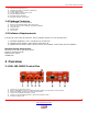
Users Guide: iMFD User Guide 3.3 Programmable SM-OBDII Your DM-100 Touch includes two products in one. It combines a DM-100 and 4 programmable SM-OBDII modules into one product. 3.3.1 Termination There are 2 options, Terminated and NOT Terminated. When the SM-OBD is terminated, it resembles the following diagram When the SM-OBD is NOT Terminated it resembles the following diagram. 11 Version 2.0 May 16, 2013 www.plxdevices.
Users Guide: iMFD User Guide 3.3.2 Data Polling Data Polling means that the SM-OBD ‘gets’ an updated value from the vehicle’s ECU (Engine Control Unit). You can choose to turn ON or OFF Data Polling for Sensors 1,2,3,4. The more sensors you have set to ON, the slower the refresh rate will be. It is recommended that you turn on data polling only on sensors you wish to monitor, for maximum performance. By default, your unit comes preset with sensor 1,2,3,4 data polling ON.
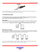
Users Guide: iMFD User Guide 3.4 Setup Sensors Sensors are automatically detected when the gauge starts up. Detected sensors are arranged in the order of the iMFD daisy chain connection. Up to 16 sensors can be detected and displayed on the DM-100 OBDII Touch. 3.5 Special Note about the DM-100 OBDII Touch If you wish to detect sensors from the SM-OBDII, you MUST connect the TX from the SM-OBD to the RX of Sensors with the supplied 1ft serial cable. See diagram below.
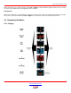
Users Guide: iMFD User Guide 4.2 Digital Gauges (Numeric) Digital gauges represent sensor data in large numeric form. Touch LEFT – RIGHT to switch between sensors. Touch DOWN to switch to plot gauges. Touch UP to switch to analog gauges. 4.3 Plot Gauges Plot gauges represent sensor data in a real-time graphical form. The sensor data is plotted on the y-axis and time is plotted on the x-axis. Touch LEFT – RIGHT to switch between sensors. Touch DOWN to switch to peak-hold.
Users Guide: iMFD User Guide 4.5 Two Parameter Gauges 2 parameter gauges represent sensor data by showing 2 sensors simultaneously on the same screen. Touch LEFT – RIGHT to switch between sensors. Touch DOWN to switch to 4 parameter view. Touch UP to switch to peak and hold gauges. 4.6 Four Parameter Gauges 4 parameter gauges represent sensor data by showing all 4 parameters simultaneously on the same screen. Touch LEFT – RIGHT to switch between sensors. Touch DOWN to switch to custom gauge view.
Users Guide: iMFD User Guide For standard users: Please visit our online custom gauge database located here http://plxdevices.com/customgauges/ You will need to install the USB device drivers and the DM-100/200 Utility before you can upload your custom gauge. The files are located here http://plxdevices.com/product_info.php?id=MULTDM100TOUCH For advanced users: This option is not recommended unless you have experience with graphic design. Steps to creating and uploading your own custom gauge: 1. 2. 3. 4.
Users Guide: iMFD User Guide YourFilename002.jpg . . . YourFilename098.jpg YourFilename099.jpg Once you’ve successfully made or obtained your 100 frames, you will need to use DM-100 Utility PC software (available from the PLX website) to upload your custom gauge to the DM-100. You can do this by connecting the DM-100 to your PC with the supplied USB cable. The DM-100 must be powered on and toggled to the setup mode “Connect to PC” for successful uploading to occur.
Users Guide: iMFD User Guide Narrowband O2 Sensor Voltage Sensor 2 Bank 1 Volts Volts Narrowband O2 Sensor Voltage Sensor 1 Bank 2 Volts Volts Narrowband O2 Sensor Voltage Sensor 2 Bank 2 Volts Volts Fuel System Status Open or Closed Open or Closed Page5: Sensor Standard Units Metric Units Barometric Pressure inHG Kpa Absolute Engine Load % % Fuel Level % % Relative Fuel Pressure PSI Kpa Ambient Air Temperature Fahrenheit Celsius Page6: Sensor Standard Units Metric Units Cat
Users Guide: iMFD User Guide The second digit identifies whether the code is a generic code (same on all OBD-II equipped vehicles), or a manufacturer specific code.
Users Guide: iMFD User Guide UP, DOWN, LEFT, RIGHT – Moves the cursor to select your desired color. LEFT – RIGHT (Simultaneously 3 seconds) – To exit the color palette. 7.2 Connect to PC The DM-100 must be in this menu for the PC to communicate with the device. Toggle to this menu if you want to upload wallpapers, custom gauge, and/or update your sensor table. 7.3 Warnings The DM-100 can monitor up to 4 parameters for warnings.
Users Guide: iMFD User Guide If the DM-100 measures the following values and the ‘scheme’ setting is set to P1 OR P2, this means that if the Parameter 1 is TRUE OR Parameter 2 is TRUE, a warning will trigger. Parameter 3 and 4 are ignored. Measured values: (Parameter 1) AFR = 14.0 FALSE (Parameter 2) EGT = 850 TRUE (Parameter 3) Oil = 105 FALSE (Parameter 4) BST = 20 TRUE Since Parameter 2 is TRUE, a warning will trigger according to the above example.
Users Guide: iMFD User Guide 7.4.1 Set Defaults This option resets the DM-100 back to factory defaults. Custom wallpapers, custom gauge and sensor tables are NOT affected. 7.4.2 Boot State This option allows you to set which gauge to be displayed when the DM-100 boots up for the first time. 7.4.3 OBD Diag In this mode, your DM-100 can be connected and controlled from the PC with additional 3rd party software. 7.4.
Users Guide: iMFD User Guide 8 Technical Specifications 8.1 DM-100 OBDII Touch Control Box Physical Dimensions (Box) Power Consumption OBDII/CAN Protocols OBDII PIDs Compatible HDD Processors Operating Temperature Operating Voltage Automatic Sensor Detection Human Interface PC Interface # Sensor Modules Firmware Upgradeable Enclosure 4" x 2.875" x 1.125" (104mm x 75mm x 28mm) L x W x H 1.