
Data Sheet


biosignalsplux
User Manual
!
!
!
40!of!159!
!
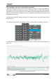
3.1.4 Electroencephalography (EEG)
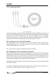
Figure 22: EEG sensor.
Our low-noise ECG local differential triode configuration enables fast application and
unobtrusive data acquisition (although custom electrode cable configurations are
available). The state-of-the-art design of the analog frontend on this sensor is specifically
targeted at analyzing minutiae in the data. Together with the Heart Rate Variability (HRV)
plugin on our OpenSignals software, one can easily record and extract meaningful
information.
Electrode cables & sleeves
The electrode cables of this sensor can be connected to electrodes with integrated stud
connectors. The colored plastic sleeves on each electrode cable indicate which electrode
must be connected to the positive, negative or reference electrode cable (see Table 4).
Electrode Cable
+
-
Reference
Sleeve Color
Red
Black
White
Table 4: Color coding of the electrode cable sleeves.
How to connect your sensor to your biosignalsplux
The EEG sensors can be connected to any of the available analog inputs of your
biosignalsplux device (see 2.3.2 Analog Inputs).
This EEG sensor has a built-in reference electrode cable. An additional reference
electrode which can be connected to the reference input of your device is not needed but
can still be used to work with this sensor (see 2.3.3 Reference) and useful when using
multiple EEG sensors during an acquisition. For optimal signal acquisition, place your
reference electrode on a region of the body with low level of muscle activity.