High Efficiency Pellet Stove PH35PS-B PH50PS-B PH50CABPS-B MODELS: PH35PS SERIES - MEDIUM PELLET STOVE WITH PEDESTAL PH50PS SERIES - LARGE PELLET STOVE WITH PEDESTAL AND BASE PAN PH50CABPS SERIES - CABINET PELLET STOVE Owner’s Manual Installation and Operation SAFETY NOTICE: PLEASE READ THIS ENTIRE MANUAL BEFORE INSTALLATION AND USE OF THIS PELLET FUEL BURNING ROOM HEATER. FAILURE TO FOLLOW THESE INSTRUCTIONS COULD RESULT IN PROPERTY DAMAGE, BODILY INJURY OR EVEN DEATH.
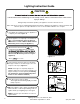
Lighting Instruction Guide CAUTION Follow all instructions and warnings for safe startup of stove. Failure to follow instructions could result in injury or damage. During startup and normal operation your appliance’s front door must be closed. Odors and vapors are released during initial startup after purchase. Burning your appliance on HI for 30 minutes will allow the paint to cure. Open windows or doors for air circulation until burn-off is complete. Turn Dial Control to OFF and ensure appliance is 1.
Safety Alert Key: • • • • DANGER! Indicates a hazardous situation which, if not avoided will result in death or serious injury. WARNING! Indicates a hazardous situation which, if not avoided could result in death or serious injury. CAUTION! Indicates a hazardous situation which, if not avoided, could result in minor or moderate injury. NOTICE: Indicates practices which may cause damage to the appliance or to property. TABLE OF CONTENTS 1 Listing and Code Approvals ..... 5 A. Appliance Certification . . .
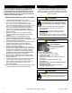
CAUTION IMPORTANT After reading these instructions, if you have any doubt about your ability to complete your installation in a professional manner you should obtain the services of an installer versed in all aspects as to the correct and safe installation. Do not use temporary makeshift compromises during installation. It is highly recommended that the pellet heater and chimney be installed by a qualified installer.
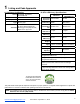
1 Listing and Code Approvals B. BTU & Efficiency Specifications A. Appliance Certification Series: PH35PS-B, PH50PS-B, PH50CABPS-B Safety Laboratory: UL LLC Emissions 0061PS095E Report No: Safety Report No. MH60687 Type: Solid Fuel Room Heater/Pellet Fuel Burning Type ASTM E1509-04 and ULC S62700, Room Heater Pellet Fuel Standard: Burning type and (UM) 84-HUD, Mobile Home Approved. PH50PS-B PH50CABPS-B PH35PS-B 19-470 Emissions OMNI Laboratory: PFS-TECO EPA Certification Number: N.A.
C. Glass Specifications This appliance is equipped with 5mm ceramic glass. Replace glass only with 5mm ceramic glass. Please contact GHP for replacement glass. D. Electrical Rating (On High) Stove Series PH35PS PH50PS PH50CABPS Electrical Rating This appliance is approved for mobile home installations when not installed in a sleeping room and when an outside combustion air inlet is provided. The structural integrity of the mobile home floor, ceiling, and walls must be maintained.
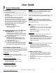
User Guide 2 General Information A. Fire Safety To provide reasonable fire safety, the following should be given serious consideration: • Install at least one smoke detector on each floor of your home. • Install at least one carbon monoxide detector on each floor of your home. • Locate smoke detector away from the heating appliance and close to the sleeping areas. • Follow the smoke detector manufacturer’s placement and installation instructions and maintain regularly.
3 General Operating Information WARNING HOT SURFACES! Glass and other surfaces are hot during operation AND cool down. Hot glass will cause burns. • Do not touch glass until it is cooled • NEVER allow children to touch glass • Keep children away • CAREFULLY SUPERVISE children in same room as appliance. • Alert children and adults to hazards of high temperatures. • High temperatures may ignite clothing or other flammable materials. • Keep clothing, furniture, draperies and other flammable materials away.
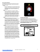
B. User Dial Control M AR AL TOMÁTICO / A UT / AU C O I AUTO M UE TIQ MA AT ON OF F X MA -3 -2 4 0 +1 4 -1 +2 +3 + - customerservice@ghpgroupinc.com AUTO MIN The appliance has one dial control located on the side of the unit used for daily operation. There are four primary settings on this dial. • Off: - When the dial indicator is in the off position the unit will go into a shut down and remain off until the dial is turned to one of the other three settings.
D. Priming the Feed Tube STOP! Please Read Prior to Attempting Prime Function When attempting Prime function it is NECESSARY to operate the dial control QUICKLY in a single fluid motion. If this is not performed properly, the appliance will not prime. OM AUT AL ÁTICO / AU T OM UE AUTO IQ AT MA T ON / IC AR M AUTO MIN OF F X MA This is the position for the dial control when starting the prime feature.
H. Fire Characteristics The overall height of the flame will vary throughout the burn for a couple of reasons. First is that the flame will vary based on type of fuel or even batch of fuel. Secondly, the appliance adjusts the burn rate according to the how far away the room temperature is from the set temperature. This should not cause alarm. The third characteristic that affects the fire relates to general maintenance and cleaning. Infrequent or poor general maintenance will result is poorer performance.
N. LED Color Coding Chart and Explanation LED Color Number of Flashes between pauses Green Steady ON while priming feed tube (max time 2 minutes) Feed Motor is running continuously. (This primes the feed tube). Green Steady ON while burning Room temperature is close to set point and burning on lowest burnt rate. Green 1x Green Blinks Continuously Green Varies Description Unit is off and ready. Appliance is in the start up/ignition sequence or in shutdown.
4 Maintaining & Servicing Your Appliance When properly maintained, your appliance will give you many years of trouble-free service. Contact your GHP dealer to answer questions regarding proper operation, troubleshooting and service for your appliance. A. Proper Shutdown Procedure Turn dial control to off, let appliance completely cool and exhaust blower must be off. After cooling unplug appliance before servicing.
C. General Maintenance 1. Types of Fuel The type of fuel you are burning will dictate how often you have to clean your firepot. If the fuel you are burning has a high dirt or ash content, it may be necessary to clean the firepot more than once a day. Poor quality fuel will cause clinkers to form in the firepot. A clinker is formed when dirt, ash or a non-burnable substance is heated to 2000°F (1093°C) and becomes glass-like. See section D following for more details on fuels with high ash content. 2.
4. Disposal of Ashes • Frequency: As needed • By: Homeowner Ashes should be placed in a metal container with a tightfitting lid. The closed container of ashes should be placed on a non-combustible floor or on the ground, well away from all combustible materials, pending final disposal. If the ashes are disposed of by burial in soil or otherwise locally dispersed, they should be retained in the closed container until all cinders have been thoroughly cooled.
7. Cleaning the Exhaust Path, Baffles & Drop Tube • Frequency: Monthly or every 25 bags or more frequently depending on ash build-up. • By: Homeowner a. Appliance must be completely cool. b. Open the door and remove the center baffle first and then the right and left baffles. Thoroughly vacuum the exhaust path and drop tube and continue throughout the rest of the firebox. Also vacuum the front and back of the baffles. c.
11. Preparing Firebox for Non-Burn Season • Frequency: Yearly • By: Homeowner a. Be sure the appliance is allowed to cool, has been unplugged and the exhaust blower is off. b. Remove all ash from the firebox and vacuum thoroughly. c. Paint all exposed steel, including cast-iron. – Purchase high temperature paint from your local retailer. – Must use a high-temperature paint made specifically for heating appliances. 12. Soot and Fly Ash: Formation & Need for Removal in Exhaust Venting System.
E. Frequently Asked Questions What causes my glass to become dirty? If the glass has white ash build up it is normal and the glass should be cleaned. If it is a black soot build up airflow through the unit may be restricted. The most often cause is overdue maintenance and cleaning. See “Maintaining and Servicing Appliance” in the owner’s manual and/or make adjustments to the trim control.
5 Replacement Parts A. Convection Blower Replacement B. Exhaust Blower Replacement 1. Turn the dial control to the off position. Unplug the power to the unit. 2. The convection blower is located in the rear of the unit. 3. Using #2 Phillips screwdriver, loosen the bolts on the rear of the unit holding on the side panels. You do not need to remove the screws. Remove side panels by lifting up and out. 4. Unplug the wires from the convection blower motor from the right side of the unit. 5.
C. Snap Disc Replacement D. Igniter Replacement Power - Manual Reset 1. Turn the dial control to the off position. Unplug the power to the unit. 2. Unplug the wire leads to the igniter. 3. Loosen the thumb screw in the side of the igniter chamber. 4. If there is difficulty in removing the igniter from the chamber, the chamber can be removed from the rear of the firebox by removing the 1/4-20 bolt. 5. Re-install the new igniter into the chamber. Ensure igniter flange it flush with back of chamber. 6.
F. Glass Replacement I. Feed Motor Replacement WARNING • • • Glass is 5mm thick high temperature heat-resistant ceramic glass. DO NOT REPLACE with any other material. Alternate material may shatter and cause injury. 1. Turn the dial control to the off position and unplug the unit. Remove the right side panel and feed motor cover plate in the rear of the unit. 2. Unplug the connector from the feed motor. 3. Using pliers, remove the cotter pin. 4. Remove the feed motor from the feed shaft. 5.
Install Guide 6 Getting Started A. Design, Installation & Location Considerations 1. Appliance Location NOTICE: Check building codes prior to installation. • • Installation MUST comply with local, regional, state and national codes and regulations. Consult insurance carrier, local building inspector, fire officials or authorities having jurisdiction over restrictions, installation inspection and permits.
B. Draft Draft is the pressure difference needed to vent appliances successfully. When an appliance is drafting successfully, all combustion by products are exiting the home through the chimney. Considerations for successful draft include: • Preventing negative pressure • Location of appliance and chimney To measure the draft or negative pressure on your appliance use a magnehelic or a digital pressure gauge capable of reading 0 - .25 inches of water column (W.C.).
7 Dimensions & Clearances B. Appliance Dimensions: PH50PS A.
C. Appliance Dimensions: PH50CAB D.
E. Hearth Pad Requirements (UL and ULC) Use a non-combustible floor protector, extending beneath appliance and to the front, sides and rear as indicated. Measure front distance “M” from the surface of the glass door.
8 Vent Information A. Chimney and Exhaust Connection 1. Chimney & Connector: Use 3 or 4 inch (76-102mm) diameter type "L" or "PL" venting system. It can be vented vertically or horizontally. 2. Mobile Home: Approved for all Listed pellet vent. If using the 3 inch (76mm) vertical Top Vent Adapter Kit or the 3 to 6 inch (76-152mm) Top Vent Offset Adapter, use Listed double wall flue connector. An authorized Outside Air Kit must be used with manufactured home installations. 3.
C. Equivalent Feet of Pipe WARNING The table below can help you calculate the equivalent feet of pipe which is a method used to determine pellet vent size. Vent surfaces get HOT, can cause burns if touched. Non-combustible shielding or guards may be required. Example of 3 Elbow-Rear Vent Termination Calculation PELLET FEET COMPONENTS # OF MULTIPLIED EQUIVALENT VENTING OF EQUIVALENT ELBOWS BY FEET COMPONENT PIPE FEET 90° Elbow 3 X 5 15 or Tee 45° Elbow X 3 Horizontal Pipe 7 X 1 7 Vertical Pipe 2 X 0.
9 Venting Systems A. Vertical - Interior - Typical Installation PREFERRED METHOD #1 C. Vertical into Existing Class A Chimney Rain Cap Rain Cap Flashing 12 in. (305mm) Minimum 12 in. (305mm) Minimum Flashing Firestop 6 in. (152mm) Class A Chimney Connector Adapter Firestop Ceiling Support 6 in. (152mm) Min. follow pipe manufacture listed clearance 6 in. (152mm) Min. Follow vent manufacturer’s clearances for reduced clearances 6 in.
D. Masonry Tapa de concreto Ducto de Arcilla refractaria con espacio libre Tapajuntas 1 pulgada (25 mm) de espacio libre con Firestop 3 pulgadas (76 mm) como mínimo 6 pulgadas (152mm) Mínimo 1 pulgada (25 mm) de espacio libre Revestimiento Limpieza Tapete para Chimenea Incombustible E. Alternate Masonry Concrete Cap Puerta de Limpieza Hermética Fireclay Flue Liner with Airspace Flashing 1 in. (25mm) Clearance with Firestop 6 in. (152mm) Minimum 1 in. (25mm) Clearance 2 in. (5.
F. Through The Wall Horizontal termination cap must be a minimum of 6 inches. (152mm) from the wall. Approved for mobile home installations. Must use 3 or 4 inch (76-102mm) “L” or “PL” listed pellet venting or Listed double wall pipe and an authorized Outside Air Kit in mobile homes.
10 Mobile Home A. Mobile Home Installation You must use an authorized Outside Air Kit for installation in a mobile home. 1. An outside air inlet must be provided for the combustion air and must remain clear of leaves, debris, ice and/or snow. It must be unrestricted while the appliance is in use to prevent room air starvation which causes smoke spillage. Smoke spillage can also set off smoke alarms. 2. The combustion air duct system must be made of metal.
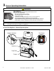
11 Appliance Set-Up A. Outside Air Kit Instructions An outside air kit has been provide standard with the appliance. It is highly recommended to use the outside air kit for maximum performance and to reduce effects from negative pressure in the home. For attachment to this platform, knock out the rectangular plate in the rear of the unit and slide the tube in the rear of the unit. Using the hose clamp, attach the flex pipe to the 2” tube welded to the rear of the firebox as shown in the photo. B.
12 Troubleshooting With proper installation, operation, and maintenance your appliance will provide years of trouble-free service. If you do experience a problem, this troubleshooting guide will assist a qualified service person in the diagnosis of a problem and the corrective action to be taken. This troubleshooting guide can only be used by a qualified service technician. Symptom Plug in appliance No response. Possible Cause No Power to outlet.
Symptom Possible Cause Dirty exhaust and/or venting system. Slow or smoky start-up and/or lazy flame Convection blower fails to start. Exhaust blower fails to start Convection Blower Does Not Turn Off Convection Blower makes noise Exhaust Blower Does Not Turn Off Igniter does not turn off Feed motor does not shut off Unit fails to shut off. Large, lazy flame, orange color. Black ash on glass.
Following correction of any Alarm, turn the dial control to the OFF position, wait 10 seconds and turn back to desired setting OR unplug the unit, wait 10 seconds then restore power. Alarm (LED Flashing RED) 1 Flash: Empty Hopper 2 Flashes: Exhaust Probe Fail The exhaust probe senses a temperature of less than negative 20 degrees Celsius or above 300 degrees Celsius. 3 Flashes: Ambient Probe Alarm The ambient probe senses a temperature of less than negative 20 degrees Celsius or above 70 degrees Celsius.
13 Reference Materials A. Component Function 1. Control Board The control board is located on the right side of the appliance behind the lower right side panel. When describing the location of a component, it is always AS YOU FACE THE FRONT OF THE APPLIANCE. 2. Convection Blower The convection blower is mounted in the rear of the unit. It pushes air up the rear of the firebox, across the top and out the front. As the air moves past the firebox it is heated. 11.
B.
C. Replacement Parts 3.2 3.3 1 2 3.1 10 12 3.1 11 2 10 10 3 9 4 8 7 6 13 12.7 12.6 12.5 5 12.4 12.3 12.2 12.1 1. Hopper Lid (1 per unit)* 2. Side Panels (2 per unit)* 3. Front Door Assembly 3.1 3.2 3.3 12. Feed Assembly Spring handle and hinge pins Door Rope Gasket and Glass Tape 5mm Ceramic Glass 4. Baffles (3 per unit)* 5. Firepot 6. Convection Blower 7. Igniter 8. Igniter Chamber 9. Exhaust Blower 10. Snap Disk, Vacuum Switch, Hopper Switch 11. Dial Control customerservice@ghpgroupinc.
D.
E. 5 Year Warranty GHP Group warrants that your new wood-burning stove, pellet-burning stove, or masonry wood insert is free from manufacturing and material defects for a period of five years from the date of sale, subject to the following conditions and limitations. 1. This warranty is extended to the original owner only, for residential use, and is subject to proof of purchase. 2.
CONTACT INFORMATION: 6440 W. Howard St. Niles, IL 60714 877-447-4768 Please contact the GHP Group with any questions or concerns. www.ghpgroupinc.com For Customer Service 1-877-447-4768 Prior to calling, please have the model, serial number, and sales receipt of the unit you are calling about. This information can be found at the rear of the unit.