THE PLASMON INFINITY LF 6602 OPTICAL DISK DRIVE User Manual P/N 97654438 E
New features and changes to information in this document are indicated by change bars. Revision level is indicated by the letter following the eight-digit document number. If a document has undergone major modifications, change bars will not be inserted in the document. Reproduction of this manual, or any portion of this manual, is prohibited without the express permission of Plasmon Laser Magnetic Storage (LMS).
WARNING Always observe the following when installing, operating or maintaining this product: • This unit must be connected to a power distribution system that has a direct connection to earth ground (Terminated Terra [TT] network/ ground connected). This unit is not suitable for use on a floating ground (Interrupted Terra [IT]) network. • The AC input power cord must be shielded and must have a minimum current rating of 10 A with a nominal cross-section area of 0.
(German Translation) WARNUNG • Bei der Installation, Bedienung und Wartung dieses Produkts, bitte immer die folgenden Vorsichtsmaßnahmen treffen: • Dieses Gerät muß an ein Stromversorgungssystem angeschlossen werden, das direkt mit einem Erdungsanschluß verbunden ist (Terminated- Terra-Netz [TT]/mit Erdanschluß). Dieses Gerät kann nicht an ein ungeerdetes Netz (Interrupted Terra [IT]) angeschlossen werden.
Radio/TV Interference (USA) The information in this section applies only to units in use within the United States: This equipment generates and uses radio frequency energy and, if not installed and used properly, that is, in strict accordance with the manufacturer's instruction, may cause interference to radio and television reception.
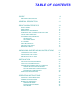
TABLE OF CONTENTS SCOPE 9 RELATED PUBLICATIONS 9 GENERAL DESCRIPTION 11 DRIVE CHARACTERISTICS 13 FRONT PANEL REAR PANEL DIMENSIONS AND WEIGHT TEMPERATURE, HUMIDITY AND ALTITUDE SHOCK AND VIBRATION AC POWER REQUIREMENTS AC GROUND AC POWER CORD TILT RANGE HEAT DISSIPATION PARTICULATE LIMITS WARNING LABELS UNPACKING AND REPACKING INSTRUCTIONS UNPACKING THE LF 6602 INSPECTING THE LF 6602 REPACKING THE LF 6602 INSTALLATION INSTALLATION REQUIREMENTS SCSI BUS CONSIDERATIONS CONNECTING POWER AND SCSI CAB
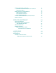
MEDIA CARTRIDGE HANDLING SETTING THE WRITE PROTECTION SWITCH AFFIXING LABELS MEDIA INSERTION AND REMOVAL MEDIA ACCESS DOOR CARTRIDGE INSERTION CARTRIDGE REMOVAL MANUAL CARTRIDGE RELEASE MECHANISM MEDIA LOADING OPERATOR MAINTENANCE ACCESSING DRIVES INSPECTING AND CLEANING FAN AND BLOWER FILTERS REPLACING FUSES MEDIA CLEANING MEDIA CLEANING USING CLEANING KIT P/N 97662550 71 73 74 74 74 76 77 78 82 83 83 85 86 87 87 ACCESSORIES 89 APPENDIX A 93 GERMAN TRANSLATIONS/ ÜBERSETZUNGEN INS DEUTSCHE 93
SCOPE This User Manual describes unpacking, installing, operating, and maintaining the Plasmon Infinity LF 6602 RapidChangert High-Performance Optical Disk Drive.
PLASMON LASER MAGNETIC STORAGE - LF 6602 USER MANUAL Page 10
GENERAL DESCRIPTION The Plasmon Infinity LF 6602 RapidChanger is a cabinet configuration, housing two LF 6600 RapidChanger drives side-by-side, as shown in the next figure. EP006028 LF 6602 Configuration Each LF 6600 drive is a write once read many (WORM), high-capacity, optical disk drive with an integral shuttle, capable of holding up to six LM 6000/LM 4000 media cartridges.
The Auxiliary Diagnostic Port (ADP), located on the rear panel of each drive, can be used to download updates to the drive firmware in the field. Refer to the LD 6100/LF 6600/LF 6602 Product Specification (P/N 97653977) for more information. Each LF 6602 drive supports a sustained read transfer rate of 2.7 MBytes/sec with error correction and defect management capabilities to maintain data integrity and manage media flaws.
DRIVE CHARACTERISTICS FRONT PANEL The LF 6602 front panel is shown in the figure below. The LF 6600 bezels, which contain the Drive Operator Console (DOC), media access door and door lock, protrude through a frame in the cabinet. A drive's bezel can be removed to gain access to that drive. Refer to the Operating Instruction section for a detailed description of the DOC.
REAR PANEL On the rear of the LF 6602 cabinet, a louvered door with a latch and a key lock covers the access to the rear of the LF 6600 drives (refer to figure below). To gain access to the drives' power switches, ADP and SCSI interface connectors, unlock the door, press up on the latch and open the door. The drives' AC power source is provided by the power socket strip, located on the bottom of the rear panel within the cabinet. The primary AC cord for the LF 6602 is connected to the power socket strip.
DIMENSIONS AND WEIGHT The LF 6602's reference dimensions, are shown in the next table. Height: 99.9 cm (39.3 in) Width: 53.6 cm (21.1 in) Depth: 81.3 cm (32.
TEMPERATURE, HUMIDITY AND ALTITUDE The following table lists the temperature, humidity and altitude limits for the LF 6600 drives installed in the LF 6602.
SHOCK AND VIBRATION The table below lists the conditions and limits for shock and vibration for the LF 6602. Shock and Vibration Criteria and Limits CONDITION Swept Vibration (Bidirectional) 1 Octave/Min Shock 3 (Host Retries May Be Required and Drive Performance May Degrade During Test OPERATING NONOPERATING1 STORAGE/TRANSIT2 5 to 22 Hz 0.01 in Double Amplitude, 22 to 500 Hz 0.25 g Peak 5 to 44 Hz, 0.03 in Double Amplitude, 44 to 500 Hz 3.0 g Peak 5 to 44 Hz, 0.
AC GROUND The LF 6602 chassis must be connected to earth ground for operator safety. The AC power cord has a grounding conductor which connects the LF 6602 chassis to safety ground through the site AC power system. If the site AC system ties its ground wire connection to earth ground, then the LF 6602 chassis will also be tied to earth ground. All site AC power connections must be maintained on the same safety ground.
WARNING LABELS The LF 6602 is classified as a laser product. As such it is subject to United States federal requirements covering laser products. The warning labels shown in the next figure are required to ensure compliance with federal regulations and must not be removed from the LF 6600 drives within the cabinet.
PLASMON LASER MAGNETIC STORAGE - LF 6602 USER MANUAL Page 20
UNPACKING AND REPACKING INSTRUCTIONS If the Laser Drive’s shipping carton shows evidence of rough handling or damage, return the unit in it’s carton to your supplier and request a replacement. UNPACKING THE LF 6602 The LF 6602 is shipped with foam packing material which protects the unit from shock and vibration. After you receive your LF 6602, inspect the shipping carton for damage before unpacking the unit to substantiate a claim with the carrier if the unit is damaged.
CARTON RAMP CUSHION BAG BANDING STRAP PLASTIC CORNER FRONT PANEL FRAME PALLET EP005015 Unpacking the LF 6602 PLASMON LASER MAGNETIC STORAGE - LF 6602 USER MANUAL Page 22
4) Cut the banding straps that secure the unit to the pallet and removes plastic corners. BANDING STRAP AND PLASTIC CORNER EP005016 Removing Banding Straps from LF 6602 5) Unlock and unlatch the LF 6602's rear door (see next figure). 6) With the LF 6602's rear door open, unfasten and remove the two bolts from the front of the frame using a 1/2 in. socket wrench. Ensure that you pull the bolts completely out of the frame. 7) Loosen, but do not remove, the two bolts on the back of the frame.
REMOVE BOLTS (2X) REMOVE SCREWS (4X), BRACKETS (2X) AND WOOD SUPPORT FRONT OF FRAME LOOSEN BOLTS (2X) BACK OF FRAME EP005017 Removing Bolts from Front of Frame; Loosening Bolts from Back of Frame PLASMON LASER MAGNETIC STORAGE - LF 6602 USER MANUAL Page 24
9) Place the ramp on the front lip of the pallet (see figure below). EP005018 Positioning Ramp on Pallet 10) With the assistance of a second person, carefully roll the LF 6602 down the ramp. WARNING To prevent personal injury, you must have a second person help you roll the LF 6602 down the ramp. When the unit is being rolled down the ramp, ensure that it is tilted no more than 10 degrees in the vertical position. The LF 6602 weighs more than 181 kg (400 lbs).
11) Re-install the front panel onto the LF 6602. 12) Carefully roll the LF 6602 to the selected operating site. NOTE Retain and store all fastening hardware and packing materials, including the wooden ramp. 13) Open the drives' media access doors and remove the small foam blocks. Manually move the shuttles all the way to the right to the home position, as shown in the next figure.
INSPECTING THE LF 6602 The following items should be included in the LF 6602 carton: • One LF 6602 • One daisy chain SCSI cable • One primary AC cord • One User Manual • One Manual Release Tool Accessories such as a SCSI terminator, a SCSI cable and optional LM 6000 media cartridges, if ordered, will accompany the LF 6602 in a separate carton.
SHIPPING BRACKET EP006031A Shipping Bracket on Rear of LF 6602 Cabinet c.) At the rear panel of each drive, insert the manual release tool into the upper access hole and engage the recessed D-shaped shaft. Turn the tool handle clockwise as far as it will turn, closing the upper baseplate. d.) Repeat step c) at the lower manual release access hole to close the lower baseplate. e.) Reposition the shipping bracket and secure it to the LF 6602 chassis by reinstalling the four screws.
UPPER ACCESS HOLE MANUAL RELEASE TOOL REAR PANEL LOWER ACCESS HOLE EP006047 Manually Closing the Drive's Baseplates 3) Ensure that the primary AC power cord is disconnected from the wall outlet and that the power switch on each drive is set to the OFF position ( O ). 4) Open each drive's media access door. Manually push each shuttle all the way to the left as shown in the next figure and insert the small foam shipping blocks to hold the shuttle in place. Close each media access door.
EP006041A Moving the Shuttle Assembly to the Shipping Position WARNING Do not attempt to lift the LF 6602 without using proper equipment. 5) Position the ramp on the front lip of the pallet. 6) With the assistance of a second person, carefully roll the LF 6602 up the ramp.
WARNING To prevent personal injury, you must have the assistance of a second person to help roll the LF 6602 up the ramp. When the LF 6602 is being rolled up the ramp, ensure that the unit is tilted no more than 10 degrees in the vertical position. The LF 6602 weighs more than 181 kg (400 lbs). If the unit is tilted more than 10 degrees, it can topple over, causing personal injury. 7) After the LF 6602 is positioned on the pallet, remove the ramp.
PLASMON LASER MAGNETIC STORAGE - LF 6602 USER MANUAL Page 32
INSTALLATION INSTALLATION REQUIREMENTS The LF 6602 is shipped as a complete assembly, ready for cable connection and power up. No tools are required for the basic installation. CAUTION Remove the foam shipping block from each of the shuttle assemblies before powering on the LF 6600 drives. Ensure that the internal temperature within the cabinet does not exceed the operating limits as described in the Product Specification (P/N 97653977) and this document.
WARNING To prevent fire or shock hazard, do not expose the LF 6602 to rain or moisture. Refer servicing to qualified technicians. In case of fire or other emergency, isolate the units from the main power by disconnecting the power plugs from their site power receptacles. In situations where disconnecting the plugs is not possible or practical, disconnect the system main power to isolate the units from the main power.
The SCSI bus must also be terminated at the host adapter end. Normally, the termination function is built into the host adapter. TERMINATOR EP006089 Host-to-LF 6602 Daisy Chain Cable Connections A terminator must always be installed on the vacant connector of the last SCSI device in the SCSI bus. The SCSI bus must always be terminated externally on the rear panel of an LF 6600 when an LF 6602 is the last SCSI device on the bus.
TERMINATOR EP006090 LF 6602-to-Host Cable Connection Normally, the termination function is built into the host adapter. Power for the external terminator is supplied by each LF 6600 and may also be supplied by another device in the SCSI daisy chain. Refer to the Accessories section of this manual for a list of SCSI bus terminators, cables and their Plasmon LMS part numbers.
CONNECTING POWER AND SCSI CABLING After the LF 6602 has been installed in its operating location, the primary AC power cord and host SCSI interface cabling can be connected. The type of primary AC power cord being installed depends upon the installation location. Perform the following procedure to install the power cabling on an LF 6602: 1) Unlock and open the LF 6602's rear door. 2) Ensure that each drive's AC power cord is securely connected to the power socket strip (see figure below).
When only one LF 6602 is being interconnected with a host, one of the SCSI interface cables is connected to the lower connector of the first drive. A terminator is connected to the lower connector of the second drive to terminate the bus when the LF 6602 is the last or only SCSI device on a SCSI bus. SINGLE-DEVICE CONFIGURATION To connect SCSI cables and a terminator on a single LF 6602: 1) Plug one end of the SCSI interface cable into the vacant SCSI interface connector on the host.
MULTIPLE-DEVICE CONFIGURATION To connect SCSI cables and a terminator, if necessary, in a multiple LF 6602 configuration, refer to the Single Device Configuration section and connect the SCSI cables according to steps 1 through 3). If the LF 6602 is part of a daisy chain configuration and is not the last unit in the chain, install one end of a SCSI interface cable into the lower connector of the second drive and then install the other end of the cable into the connector of the next device in the chain.
EXTENSION PROCEDURES If, during installation, you need to extend and access a drive through the front of the LF 6602: 1) Using a T-15 screwdriver, loosen the shipping bracket from the rear of the LF 6602 by unfastening the four screws that secure the shipping bracket to the LF 6602 chassis (see figure below). SHIPPING BRACKET EP006031A Location of Shipping Bracket on Rear of LF 6602 Cabinet 2) Pull off the cabinet's trim panel (see next figure).
WARNING Do not defeat the LF 6602's interlock and do not extend both drives simultaneously. TRIM PANEL CAUTION LABEL INTERLOCK EP006083 LF 6602 Cabinet Configuration Showing Interlock Location 4) After you have finished, return the extended drive to its original position in the cabinet; remount the shipping bracket on the rear of the cabinet and secure the bracket by reinstalling the four screws. 5) Re-install the cabinet's trim panel.
PLASMON LASER MAGNETIC STORAGE - LF 6602 USER MANUAL Page 42
OPERATING INSTRUCTIONS CONTROLS AND INDICATORS The Drive Operator Console (DOC) for each drive is located on the front panel of the LF 6602. The DOC provides the controls and indicators that enable a user to operate each LF 6600. The DOC controls and indicators consist of an alphanumeric display, a LOAD/MENU switch, a TEST/ SELECT switch, and a WRITE PROTECT indicator. For a description of the DOC controls and indicator refer to the next table.
DOC Controls and Indicator for each Drive CONTROL/ INDICATOR TYPE PURPOSE/FUNCTION Alphanumeric Display 12 - Character Dot Matrix Displays operating, configuration and test status messages. LOAD/MENU Switch Dual Function Push Button Switch In operating mode, the LOAD/MENU switch controls the loading and unloading of media cartridges. In Configuration mode, the LOAD/ MENU switch steps through the menu of configurable parameters.
POWER-ON PROCEDURE Perform the following procedure to power on each LF 6600: 1) Ensure that the LF 6600 is properly connected (refer to the SCSI Bus Consideration section). 2) Refer to the Media Insertion and Removal section and insert a cartridge into slot 1. If slot 1 is empty, the LF 6600 will display "1 Empty" on the DOC shortly after initial power on. NOTE Slot 1 is the factory setting for the media autoload configuration option.
MODES OF OPERATION The LF 6600 has three modes of operation that are selectable from the DOC: • Operating Mode • Configuration Mode • Test Mode In Operating mode the host system can read and write data, and select and load media cartridges. In Configuration mode an operator can view a menu of parameters and select options for each parameter. Test mode invokes drive diagnostics to verify proper drive operation.
NOTE The pound symbol #, shown in the table below, designates the slot number.
CONFIGURATION MODE Configuration mode is used to view and set each of the LF 6600 drive operating parameters. The parameters that can be configured and displayed are summarized in the following (the corresponding DOC display is shown in parentheses).
Entry to Configuration mode starts with a Main menu, allowing the user to select one of four submenus. The Main menu includes the following submenu options: "View Config" This is the entry point into the Configuration menu. Press the SELECT switch to enter a submenu allowing the user to view the drive operating parameters, firmware revisions and hardware serial numbers. Press the MENU switch to select the next option in the Main menu.
DOC DISPLAY View Config SELECT ENTER VIEW CONFIG MENU SELECT ENTER SET CONFIG MENU SELECT ENTER DIAGNOSTIC MENU SELECT ENTER SERIAL NUMBER ENTRY MENU MENU PRESS BOTH SWITCHES SIMULTANEOUSLY TO RETURN TO MAIN MENU "Set Config" Set Config MENU Diagnostics MENU Set Serial # MENU Main Menu PLASMON LASER MAGNETIC STORAGE - LF 6602 USER MANUAL Page 50
VIEWING THE CONFIGURATION ("VIEW CONFIG") To view the configuration, press the TEST/SELECT switch while "View Config" is displayed in the Main menu. The drive will enter the View Configuration menu which includes the following options: "View Current" Press the SELECT switch to display the current drive operating parameters. The operating parameters are listed in the table below. Press the MENU switch to select the next option in the View Configuration menu.
To exit the Configuration mode, press the LOAD/MENU and TEST/SELECT switches simultaneously from the Main menu. The display will show the message which appeared prior to the drive entering the Configuration mode.
SETTING THE CONFIGURATION OF THE OPERATING PARAMETERS ("SET CONFIG") To enter the mode to set the drive configuration, press the TEST/SELECT switch while "Set Config" is displayed in the Main menu. The drive will enter the Set Configuration menu which includes the following options: "Set Defaults" Press the SELECT switch to set all drive operating parameters to the factory defaults. Press the MENU switch to select the next option in the Set Configuration menu.
"Busy" Press the SELECT switch to toggle the Busy option between On and Off. When the desired mode has been selected, press the LOAD/MENU switch to select the next option. "ModSel RA" Press the SELECT switch to toggle the Mode Select Read Ahead option between On and Off. When the desired mode has been selected, press the LOAD/MENU switch to select the next option. "MM SpinUp" Press the SELECT switch to toggle the Media Management Spin Up option between On and Off.
SET VALUES TO DEFAULT SELECT SET DEFAULT MENU SCSI ID 0 SELECT 0 7 MENU PRESS BOTH SWITCHES SIMULTANEOUSLY TO RETURN TO MAIN MENU "Set Config" SELECT PARITY ON ON OFF MENU SELECT LANGUAGE ENG ENG FRH GRM MENU SELECT WrtProt OFF ON OFF MENU SELECT AutoLoad 1 2 .
SELECT A Rd Ahead OFF OFF ON MENU SELECT PRESS BOTH SWITCHES SIMULTANEOUSLY TO RETURN TO MAIN MENU "Set Config" CDE Curs OFF OFF ON MENU SELECT Busy ON ON OFF MENU SELECT ModSel RA ON ON OFF MENU SELECT MM SpinUp ON ON OFF MENU Set Config Menu (Part 2) PLASMON LASER MAGNETIC STORAGE - LF 6602 USER MANUAL Page 56
SETTING THE SCSI ID The SCSI ID can be set to one of eight device Identification (ID) numbers (0 through 7); however, each device connected to the same SCSI bus must have a different SCSI ID. Perform the following procedure to set the LF 6600's SCSI ID number: 1) Enter the Configuration mode by pressing both the LOAD/MENU and TEST/SELECT switches simultaneously. 2) Press the MENU switch until "Set Config" is displayed. 3) Press the SELECT switch to enter the Set Configuration menu.
SETTING THE LANGUAGE The language option enables the user to select the language used by the LF 6600 to display messages in the Operating mode. (English is the only available language for Configuration mode.) Perform the following procedure to set the operating mode display language. 1) Enter the Configuration mode by pressing both the LOAD/MENU and TEST/SELECT switches simultaneously. 2) Press the MENU switch until "Set Config" is displayed. 3) Press the SELECT switch to enter the Set Configuration menu.
SETTING THE MEDIA AUTOLOAD OPTION The media AutoLoad load option enables a user to choose which media cartridge is automatically inserted and loaded at power up and whenever the LOAD/MENU switch is pressed while in the Operating mode. The factory default selects the cartridge in slot 1. Perform the following procedure to set the LF 6600's AutoLoad option: 1) Enter the Configuration mode by pressing both the LOAD/MENU and TEST/SELECT switches simultaneously.
SETTING THE READ AHEAD OPTION The read ahead option often improves the overall read data transfer rate of the LF 6600 in applications which require continuous blocks of data to be read (as compared to the same subsystem without read ahead). Perform the following procedure to turn read ahead on or off. 1) Enter the Configuration mode by pressing both the LOAD/MENU and TEST/SELECT switches simultaneously. 2) Press the MENU switch until "Set Config" is displayed.
5) Press the SELECT switch to scroll through the states for CDE Curs (on, off). When the desired state is displayed, press MENU to enter the state and move to the next option in the Set Configuration menu. 6) Simultaneously press the LOAD/MENU and TEST/SELECT switches to exit the Configuration mode. Simultaneously press the LOAD/MENU and TEST/SELECT Switches again to move up to the Main menu.
SETTING THE MM SPINUP OPTION When the enabled, the (Media Management Spin Up) MM SpinUp option allows the LaserDrive to read necessary media management information during spin up. If not enabled, the media management information will recovered on the first media access command. Perform the following procedure to enable or disable the MM SpinUp option. 1) Enter the Configuration mode by pressing both the LOAD/MENU and TEST/SELECT switches simultaneously.
VIEWING DIAGNOSTIC RESULTS OR PERFORMING DIAGNOSTIC OPERATIONS ("DIAGNOSTICS") To enter the diagnostic submenu, press the TEST/SELECT switch while "Diagnostics" is displayed in the Main menu. The drive will enter the Diagnostics menu which includes the following options: "Park Drive" Press the SELECT switch to park the baseplates for drive shipment. If the "Park Failed, Close Manually" message appears, refer to the Manual Release section of this manual.
"Sys Log:" Press the SELECT switch to enable or disable system event logging. The log can be used by a trained CE to help in problem isolation or for performance monitoring. Drive performance will be slowed and may not meet specification if logging is enabled. The default is "Sys Log Off". Press the MENU switch to select the next option in the Diagnostics Menu. "Test Thru:" Press the SELECT switch to set the level of diagnostics tests which will be performed during selftest (refer to the next table).
"Clear RTPM" CAUTION RTPM errors indicate the drive or media require maintenance, and place the drive in a read only mode. Corrective action may be as simple as cleaning the media that caused the error, or may require the attention of a trained Customer Engineer (CE) to repair the drive. Clearing this error without resolving the cause may reduce the total media capacity because of abnormally high relocations during write operations.
Park Drive SELECT MENU SELECT Test Sensors Enter Sensor Display Mode SELECT MENU PRESS BOTH SWITCHES SIMULTANEOUSLY TO RETURN TO MAIN MENU "Set Config" SELECT Confirm Clear Clear NV RAM SELECT MENU SELECT Confirm Cal Shuttle Cal Shuttle SELECT MENU View CDEs SELECT Display Default Information MENU SELECT OFF OFF Sys Log ON MENU SELECT Test Thru 00 00 01 .
A SELECT View RTPM PRESS BOTH SWITCHES SIMULTANEOUSLY TO RETURN TO MAIN MENU "Set Config" Display RTPM Information MENU SELECT RTPM True Y Confirm Clear N SELECT Clear RTPM No RTPM Err RTPM Condition is Cleared MENU SELECT Init DPC Reset Drive Init Done Self Test MENU Diagnostic Menu (Part 2) SET THE INTERNAL DRIVE SERIAL NUMBER ("SET SERIAL #") To enter the serial number submenu, press the TEST/SELECT switch while "Set Serial #" is displayed in the Main menu.
4) If the serial number does not require revision, simultaneously press the LOAD/MENU and TEST/SELECT switches to move up to the Main menu. Simultaneously press the LOAD/ MENU and TEST/SELECT switches again to exit Configuration mode. If the serial number requires revision, press the MENU switch until the digit position to be changed is blinking. Then press the SELECT switch until the desired digit value is displayed.
SELECT 0 DRV SN 1 2 3 4 . . 5 9 Blank MENU PRESS BOTH SWITCHES SIMULTANEOUSLY TO RETURN TO MAIN MENU "Set Config" SELECT 0 DRV SN 1 2 3 4 . . 5 9 Blank MENU SELECT 0 DRV SN 1 2 3 4 . . 5 9 Blank MENU SELECT 0 DRV SN 1 2 3 4 . . 5 9 Blank MENU SELECT 0 DRV SN 1 2 3 4 . .
TEST MODE Each LF 6600 automatically enters the Test mode each time it is powered on. Power-on selftest diagnostics are run to verify the operational readiness of the drive. After the LF 6600 successfully passes the power-on selftests, the drive enters the Operating mode. When the LF 6600 is in the Operating mode, the operator may manually enter the Test mode and invoke the system function diagnostics.
MEDIA CARTRIDGE HANDLING The LM 6000 media is used in all LD 6100/LF 6600/LF 6602 drives. The LM 6000 media cartridge, illustrated in the next figure, is shipped ready for immediate use and does not require preformatting.
Observe the following precautions to ensure data integrity when handling or storing a media cartridge: 1) Do not drop the media cartridge onto hard surfaces. 2) Do not physically abuse the cartridge exterior or access mechanisms. 3) Do not store the media cartridge in the drive. 4) Remove cartridges from the drive when the drive is going to be moved. 5) Apply labels only in designated areas. Refer to the Affixing Label section for instructions on label placement.
SETTING THE WRITE PROTECTION SWITCH To manually write protect a cartridge, set the write protect switch on the data cartridge as indicated in the next figure.
AFFIXING LABELS Title and content labels are supplied with each LM 6000 media cartridge and should be affixed before the cartridge is inserted into the LF 6600. Before affixing the labels in the recessed areas (see figure below), ensure that the surface of the cartridge is clean and dry. SIDE A VIEW POSITION LABELS HERE EP004111 Label Placement MEDIA INSERTION AND REMOVAL MEDIA ACCESS DOOR Individual media cartridges are inserted and removed through the front panel media access door.
ELECTRICAL SAFETY LOCK LATCH KEY LOCK LATCH DOOR SAFETY SWITCH TAB KEY LOCK EP006026 LF 6600 Media Access Returning the shuttle to home can be accomplished by host command or by pressing LOAD/MENU at the DOC. If access is authorized, the drive will unload the media cartridge into the shuttle, move the shuttle to the home position, and unlock the electrical safety door lock.
CARTRIDGE INSERTION LM 6000 media cartridges are inserted directly into the LF 6600 shuttle via the media access door described in the Media Access Door section. Ensure that the arrows on the cartridge point toward the shuttle and insert the cartridge into the slot until it is fully seated and its back edge is flush with the edge of the shuttle.
CARTRIDGE REMOVAL LM 6000 media cartridges may be removed from the media access door. To aid in removing the closely spaced cartridges, the top rear edge of the shuttle is cut away and a notch is provided on the exposed edge of each cartridge. Pulling on the cartridge notch with one finger as shown in the next figure, will back the cartridge out far enough so that it can be grasped and removed.
MANUAL CARTRIDGE RELEASE MECHANISM If power fails or if the drive fails with a media cartridge inserted, the media cartridge can be manually removed by opening the drive baseplates, removing the bezel and then retracting the cartridge. OPENING THE BASEPLATES With the manual release tool, perform the following procedure: 1) Move the AC power switch to the OFF ( O ) position and disconnect the AC power cable from the wall outlet.
REMOVING THE BEZEL NOTE A T15 screwdriver is required for removing the bezel assembly. 1) Release the electrical safety door lock by inserting the flat handle end of the manual release tool through the slot in the bezel and move the locking lever to the left out of the door lock tab as shown below.
CHASSIS ASSEMBLY MOUNTING HOOKS DOOR SAFETY SWITCH CABLES M4 X 20 SCREW BACK VIEW OF BEZEL BEZEL DOOR SAFETY SWITCH HOOK RESTS EP006044 Bezel Removal PLASMON LASER MAGNETIC STORAGE - LF 6602 USER MANUAL Page 80
RETRACTING THE CARTRIDGE 1) Insert the manual release tool onto the D-shaped shaft at the front of the drive as shown below to operate the cartridge insertion mechanism. Turn the tool clockwise as far as it will turn, pulling the cartridge back into the shuttle.
2) Manually move the shuttle to the home position as shown below. EP006039 Manually Moving the Shuttle Assembly to the Home Position 3) Remove the cartridge from the shuttle slot. MEDIA LOADING Individual media cartridges can be selected for loading by host command or by the autoload configuration option. The host can select and load a media cartridge from any shuttle slot by issuing an appropriate SCSI bus command.
OPERATOR MAINTENANCE ACCESSING DRIVES During operator maintenance, if you need to extend and access a drive through the front of the LF 6602, perform this procedure: 1) Disconnect a drive from the shipping bracket at the rear of the LF 6602 by unfastening the four M4 screws (see figure below). SHIPPING BRACKET EP006031A Disconnecting a Drive from the Shipping Bracket 2) Pull off the cabinet's trim panel (see next figure).
WARNING Do not defeat the LF 6602's interlock and do not extend both drives simultaneously. TRIM PANEL CAUTION LABEL INTERLOCK EP006083 LF 6602 Cabinet Configuration Showing Interlock Location 4) After you have finished, return the extended drive to its original position in the cabinet; remount the shipping bracket on the rear of the cabinet and secure the bracket by reinstalling the four screws. 5) Re-install the cabinet's trim panel.
INSPECTING AND CLEANING FAN AND BLOWER FILTERS Two filters located on the drive's rear panel remove contaminants from air pulled into the drive (see figure below). FILTER ELEMENT OUTER FAN GRIL HALF EP006088 Removing Filter Element from Fan Inspect the Filters at the rear of the drive on a 1 - 6 month schedule and clean, if necessary, to ensure that cooling air flow is not restricted. If the drive is exposed to excessive amounts of dust, decrease the time between inspection intervals.
Perform the following procedure to clean the fan filter elements: 1) Unlock and open the cabinet door. 2) Set each drive's AC power switch to the OFF ( O ) position and verify that the fan and blower have stopped running. 3) Remove each Outer Grill Half by grasping its sides and pulling it away from the chassis. 4) Remove each Filter Element by pulling it away from the inside of the Grill. 5) Wash each Filter Element in warm soapy water. 6) Rinse each Element thoroughly and let it air dry.
3) Gently pry the fuse holder open. Slide the fuse holder out of the receptacle and visually inspect the active fuse to determine if it is blown. If the active fuse is blown, proceed to step 4); otherwise, proceed to 5). 4) Remove the active fuse and discard it. Remove the spare fuse from its storage location and insert the fuse between the fuse housing and the retaining clip.
PLASMON LASER MAGNETIC STORAGE - LF 6602 USER MANUAL Page 88
ACCESSORIES The following accessories are available from Plasmon LMS. The cables listed in the table below can be purchased to connect product and host. All Plasmon SCSI cables are shielded and can be used for both Differential and Single Ended applications. Optional SCSI Cables PLASMON Part Number Length Connector A Connector B 77050622 1 M (3.3 ft) 50 pin high-density Alt 1-A cable-Male, Rt angle 50 pin high-density Alt 1-A cable-Male, Rt angle 97654406 1 M (3.
The table below contains optional SCSI accessories such as terminators and adapters that can be purchased to connect the drive to the host.
Differential and Single - ended Cable Kits PLASMON Part Number Product Description Includes SP97660827 Kit, Cable, Differential, US 15165428, 97653429 SP97660828 Kit, Cable, Differential, EUR 97646185, 97653429 SP97660829 Kit, Cable, Differential, UK 97646184, 97653429 SP97660830 Kit, Cable, S/E, US 15165428, 97653428 SP97660831 Kit, Cable, S/E, EUR 97646185, 97653428 SP97660832 Kit, Cable, S/E, UK 97646184, 97653428 The table below contains optional power cable part numbers for each co
PLASMON LASER MAGNETIC STORAGE - LF 6602 USER MANUAL Page 92
APPENDIX A GERMAN TRANSLATIONS / ÜBERSETZUNGEN INS DEUTSCHE ABMESSUNGEN UND GEWICHT Die Bezugsabmessungen für den LF 6602 (wie auch aus Abbildung 4 ersichtlich) betragen wie folgt: Höhe: 99.9 cm Breite: 53.6 cm Tiefe: 81.3 cm Der LF 6602 wiegt 204 kg. TEMPERATUR, LUFTFEUCHTIGKEIT UND SEEHÖHE In Tabelle 1 sind die Temperatur-, Luftfeuchtigkeits- und Meereshöhengrenzwerte für die im LF 6602 installierten LF 6600-Laufwerke aufgeführt. Tabelle 1.
1 Die Lagerungsangaben beziehen sich auf maximal 90 Tage in der Plasmon LMS-Verpackung. Kondensation ist nicht zulässig. Die Transportangaben gelten für maximal 1 Woche in einem werkseitig verschlossenen Behälter. 2 Falls nicht anders angegeben ist die maximale Betriebstemperatur für ein freistehendes Laufwerk auf Meereshöhe. 42 C. Die maximale Betriebstemperatur über 300 m Höhe wird bei 2000 m Höhe linear auf 38 C herabgesetzt.
Das Netzteil ist selbstregulierend und erfordert kein mechanisches Schalten der Eingangsspannung oder Netzfrequenz. Tabelle 3. Wechselstrombedarf FREQUENZ WECHSELSPANNUNG LEISTUNG (TYPISCH) EINSCHALTSTROMSTOSS1 NENNLEISTUNG, MIN 47 bis 66 Hz 86,7 bis 128 V 3,0 A 10.0 A 15 A 47 bis 66 Hz 173,4 bis 268 V 1,5 A 5.0 A 15 A 1 Weniger als 1 Sek., Kaltstarthinweis HINWEIS Nach Ausschalten des Stroms müssen Sie 1 Sekunde warten, bevor der Strom wieder eingeschaltet werden darf.
AUSPACHEN DER LF 6602 WARNUNG Um Personenverletzungen zu vermeiden, darf der LF 6602 nicht ohne geeignete Hilfsvorrichtungen angehoben werden. Beim Auspacken und Transport des LF 6602 ist sicherzustellen, daß die Einheit um nicht mehr als 10 Grad gekippt wird. Der LF 6602 wiegt über 181 kg. Wenn die Einheit um mehr als 10 Grad gekippt wird, kann sie unversehens umfallen und zu Personenverletzungen führen.
WARNUNG Um Personenverletzungen zu vermeiden, sind zwei Personen erforderlich, um den LF 6602 auf einer Rampe nach oben zu rollen. Hierbei ist sicherzustellen, daß die Einheit um nicht mehr als 10 Grad gekippt wird. Der LF 6602 wiegt über 181 kg. Wenn die Einheit um mehr als 10 Grad gekippt wird, kann sie unversehens umfallen und zu Personenverletzungen führen.
WARNUNG Um Brand oder Elektroschock zu vermeiden, darf der LF 6602 weder Regen noch Feuchtigkeit ausgesetzt werden. Wartungsarbeiten dürfen nur von qualifizierten Technikern ausgeführt werden. Trennen Sie die Einheiten im Falle eines Brandes oder einer anderen Notsituation von der Hauptstromversorgung, indem Sie die Stecker aus den Steckdosen ziehen. Sollte das Herausziehen der Stecker nicht möglich oder praktisch sein, trennen Sie die Hauptstromversorgung.
WARNUNG Setzen Sie die Verriegelung des LF 6602 nicht außer Kraft, und öffnen Sie nicht beide Laufwerke gleichzeitig. EINSCHALTVERFAHREN HINWEIS Die Seriennummer, die dem Laufwerk zugeordnet wird, muß mit den letzten 5 Ziffern der tatsächlichen Seriennummer des Laufwerks übereinstimmen, damit eine exakte interne Ereignisprotokollierung stattfinden kann. Die tatsächliche Seriennummer des Laufwerks befindet sich an der Rückseite des Laufwerksgehäuses.
EINSTELLEN DER INTERNEN LAUFWERKSSERIENNUMMER ("SERIENNR. EINSTELLEN") HINWEIS Die Seriennummer, die dem Laufwerk zugeordnet wird, muß mit den letzten 5 Ziffern der tatsächlichen Seriennummer des Laufwerks übereinstimmen, damit eine exakte interne Ereignisprotokollierung stattfinden kann. Die tatsächliche Seriennummer des Laufwerks befindet sich an der Rückseite des Laufwerksgehäuses.
12) Die Datenträgerkassetten in einer sauberen Büroumgebung benutzen, handhaben und lagern. 13) Während der Handhabung von Datenträgern nicht rauchen. Asche und Tabak sind eine Hauptquelle für die Verunreinigung von Magnetplatten. Alle Rauchutensilien sind aus den Bereichen fernzuhalten, in denen Datenträger benutzt oder gelagert werden. 14) 14) Die Außenflächen der Kassetten sauber halten. Die Kassetten regelmäßig mit einem weichen, trockenen, fusselfreien Tuch reinigen.
3) Öffnen Sie den Sicherungshalter vorsichtig. Ziehen Sie den Sicherungshalter aus der Buchse heraus und überprüfen Sie die aktive Sicherung, um festzustellen, ob sie durchgebrannt ist. Wenn die Sicherung durchgebrannt ist, fahren Sie mit Schritt 4) fort, ansonsten mit Schritt 5). 4) Entfernen Sie die aktive Sicherung und entsorgen Sie sie. Nehmen Sie die Ersatzsicherung aus deren Aufbewahrungsort und fügen Sie die Sicherung zwischen dem Sicherungsgehäuse und der Halteklammer ein.