00Base-FX to 10/100Base-TX PoE Media Converter FCU-1802Px User’s Manual
Trademarks Copyright © Antaira Technologies 2013. Contents subject to revision without prior notice. Antaira is a registered trademark of Antaira Technologies. The information in this manual is subject to change without notice. All other trademarks belongs to their respective owners.
FCC Warning This equipment has been tested and found to comply with the regulations for a Class A digital device, pursuant to Part 15 of the FCC Rules. These limits are designed to provide reasonable protection against harmful interference when the equipment is operated in a commercial environment. This equipment generates, uses, and can radiate radio frequency energy and, if not installed and used in accordance with this user’s guide, may cause harmful interference to radio communications.
WEEE Warning To avoid the potential effects on the environment and human health as a result of the presence of hazardous substances in electrical and electronic equipment, end users of electrical and electronic equipment should understand the meaning of the crossed-out wheeled bin symbol. Do not dispose of WEEE as unsorted municipal waste and have to collect such WEEE separately. Revision User’s manual for Antaira 100Base-FX to 10/100Base-TX PoE Media Converter Rev 1.1 (April 2013) Part No.
Table of Contents 1. Overview ......................................................................... 6 2. Model List ........................................................................ 7 3. Checklist .......................................................................... 7 4. Product Outlook ................................................................ 8 5. Link Fault Pass through (LFP)........................................... 10 6. Installing the Converter ..................................
1. Overview Thank you for purchasing Antaira's FCU-1802Px family of 10/100Mbps Ethernet Twisted pair to 100Base-FX Fiber-optic PoE Bridge Converter. This converter is used to convert one type media signal to another easily, efficiently and inexpensively. The converter provides Power over Ethernet power injector function which is able to drive one IEEE 802.3af compliant powered devices. About the Power over Ethernet Injector The FCU-1802Px has an IEEE 802.
2. Checklist Your FCU-1802Px package should contain the following items: ● 100Base-FX to 10/100Base-TX PoE Media Converter x 1 ● AC-DC Power Adapter (Input: 48V DC, 0.4A max.) x 1 ● User’s Manual x 1 If any items are missing or damaged, please consult the dealer from which you purchased your PoE Media Converter.
3. Product Outlook Overview Layout of the FCU-1802Px.
Left View There are one RJ-45 Twisted-Pair jack (Auto-MDI/MDI-X), one fiber-optic connector (vary by model) and four LED indicators. TX RX FX TP LNK/ ACT PWR PoE PoE Media Converter In Use 10/100Base-TX to 100Base-FX 10/100Base-TX Right View One DIP switch “ON” to turn-on –off this feature. Also one DC 48V for Link Fault Pass Through (LFP) feature, the LLCF and LLR detection. And “OFF” to turn Please refer to the following sections for more. power socket for the PoE Media Converter.
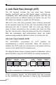
4. Link Fault Pass through (LFP) The LFP function includes the Link Fault Pass Through function (LLCF/LLR) and the DIP Switch design. LLCF/LLR can immediately alert administrators about problems with the link media and provide an efficient solution to monitor the net. The DIP Switch can disable or enable the LFP function. With LLCF (Link Loss Carry Forward), when a device connected to the converter loses the TP line link, the converter’s fiber will disconnect the link of transmit.
station. The administrator can then determine the source of the problem. Management Station Switch/Hub w/SNMP Media Converter Media Converter LFP ON l LED lit = established link Management Station LFP ON Broken Fiber Cable TP Switch/Hub w/SNMP TP ° LED unlit = no link *Units are shipped with the LFP function disable (OFF). Link Loss Return (LLR) The fiber ports of the FCU-1802Px have been designed with an LLR function for troubleshooting a remote connection. LLR works in conjunction with LLCF.
If one of the optical conductors is bad (as shown in the diagram box below), the converter with LLR function will return a no-link condition to its link partner. With LLCF function also enabled, the no-link condition is carried forward to the switch/hub where a trap is generated to the management station, and the administrator can then determine the source of the loss.
5. Installing the Converter Please follow these steps to install the PoE Media converter: ● Turn off the power of the device/station on the network to which the FCU-1802Px will be attached. ● Ensure that there is no activity in the network. ● Attach fiber cable from the FCU-1802Px to the fiber network. TX, RX must be paired at both ends. ● Attach a Cat. 5 UTP cable from the 10/100Base-TX network to the RJ-45 port on the FCU-1802Px.
6. PoE function FCU-1802Px and the IEEE 802.3af Injector / Splitter equipment installation: Before your installation, it is recommended to check your network environment. If there is any IEEE 802.3af devices that need to power on, the FCU-1802Px can provide a way to supply power for this Ethernet device conveniently and easily. The FCU-1802Px comes with an AC-DC adapter with DC 48V input and injects this DC power into the pin of the twisted pair cable (pair 1, 2 and pair 3, 6).
7. LED indication • System LED Color PWR Green Function Lit: Indicate the device is powered. • 10/100Base-TX Port LED Color LNK/ACT Green Function Indicate that the Media Converter Blink is actively sending or receiving data over that port. Lit PoE in Use Indicate that the port is link up. Off Indicate that the port is link down. Lit Indicate that the port is providing 48VDC to remote powered device. Off Indicate that the port is not providing 48VDC to remote powered device.
8. Cable Connection Parameter The limitations are as below: Duplex Connection Limitation (max.
9. FCU-1802Px Technical Specifications The FCU-1802Px comes with the following standard features: ● Standard: IEEE 802.3u, 10/100Base-TX ,100Base-FX IEEE 802.
APPENDIX A A.1 Device's RJ-45 Pin Assignments • 10/100Mbps, 10/100Base-TX MDI-X Contact MDI 1 1 (TX +) 3 2 2 (TX -) 6 3 3 (RX +) 1 6 6 (RX -) 2 4, 5, 7, 8 Not used Not used Implicit implementation of the crossover function within a twisted-pair cable, or at a wiring panel, while not expressly forbidden, is beyond the scope of this standard. A.2 RJ-45 cable pin assignment There are 8 wires on a standard UTP/STP cable and each wire is color-coded.
Figure A-1: Straight-Through and Crossover Cable Please make sure your connected cables are with the same pin assignment and color as the above picture before deploying the cables into your network. A.3 Fiber Optical Cable Connection Parameter The wiring details are as below: • Fiber Optical patch Cables: Standard Fiber Type Cable Specification 100Base-FX (1310nm) Multi-mode 50/125μm or 62.
This page is intentionally left blank