
User Manual

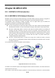


Table Of Contents
- Chapter 1 INTRODUTION
- Chapter 2 INSTALLATION
- Chapter 3 Switch Management
- Chapter 4 Basic Switch Configuration
- Chapter 5 File System Operations
- Chapter 6 Cluster Configuration
- Chapter 7 Port Configuration
- Chapter 8 Port Isolation Function Configuration
- Chapter 9 Port Loopback Detection Function Configuration
- Chapter 10 ULDP Function Configuration
- Chapter 11 LLDP Function Operation Configuration
- Chapter 12 Port Channel Configuration
- Chapter 13 Jumbo Configuration
- Chapter 14 EFM OAM Configuration
- Chapter 15 VLAN Configuration
- Chapter 16 MAC Table Configuration
- Chapter 17 MSTP Configuration
- Chapter 18 QoS Configuration
- Chapter 19 Flow-based Redirection
- Chapter 20 Egress QoS Configuration
- Chapter 21 Flexible QinQ Configuration
- Chapter 22 Layer 3 Forward Configuration
- Chapter 23 ARP Scanning Prevention Function Configuration
- Chapter 24 Prevent ARP, ND Spoofing Configuration
- Chapter 25 ARP GUARD Configuration
- Chapter 26 ARP Local Proxy Configuration
- Chapter 27 Gratuitous ARP Configuration
- Chapter 28 Keepalive Gateway Configuration
- Chapter 29 DHCP Configuration
- Chapter 30 DHCPv6 Configuration
- Chapter 31 DHCP option 82 Configuration
- Chapter 32 DHCPv6 option37, 38
- Chapter 33 DHCP Snooping Configuration
- Chapter 34 Routing Protocol Overview
- Chapter 35 Static Route
- Chapter 36 RIP
- Chapter 37 RIPng
- Chapter 38 OSPF
- Chapter 39 OSPFv3
- Chapter 40 BGP
- 40.1 Introduction to BGP
- 40.2 BGP Configuration Task List
- 40.3 Configuration Examples of BGP
- 40.3.1 Examples 1: configure BGP neighbor
- 40.3.2 Examples 2: configure BGP aggregation
- 40.3.3 Examples 3: configure BGP community attributes
- 40.3.4 Examples 4: configure BGP confederation
- 40.3.5 Examples 5: configure BGP route reflector
- 40.3.6 Examples 6: configure MED of BGP
- 40.3.7 Examples 7: example of BGP VPN
- 40.4 BGP Troubleshooting
- Chapter 41 MBGP4+
- Chapter 42 Black Hole Routing Manual
- Chapter 43 GRE Tunnel Configuration
- Chapter 44 ECMP Configuration
- Chapter 45 BFD
- Chapter 46 BGP GR
- Chapter 47 OSPF GR
- Chapter 48 IPv4 Multicast Protocol
- 48.1 IPv4 Multicast Protocol Overview
- 48.2 PIM-DM
- 48.3 PIM-SM
- 48.4 MSDP Configuration
- 48.4.1 Introduction to MSDP
- 48.4.2 Brief Introduction to MSDP Configuration Tasks
- 48.4.3 Configuration of MSDP Basic Function
- 48.4.4 Configuration of MSDP Entities
- 48.4.5 Configuration of Delivery of MSDP Packet
- 48.4.6 Configuration of Parameters of SA-cache
- 48.4.7 MSDP Configuration Examples
- 48.4.8 MSDP Troubleshooting
- 48.5 ANYCAST RP Configuration
- 48.6 PIM-SSM
- 48.7 DVMRP
- 48.8 DCSCM
- 48.9 IGMP
- 48.10 IGMP Snooping
- 48.11 IGMP Proxy Configuration
- Chapter 49 IPv6 Multicast Protocol
- Chapter 50 Multicast VLAN
- Chapter 51 ACL Configuration
- Chapter 52 802.1x Configuration
- 52.1 Introduction to 802.1x
- 52.2 802.1x Configuration Task List
- 52.3 802.1x Application Example
- 52.4 802.1x Troubleshooting
- Chapter 53 The Number Limitation Function of Port, MAC in VLAN and IP Configuration
- 53.1 Introduction to the Number Limitation Function of Port, MAC in VLAN and IP
- 53.2 The Number Limitation Function of Port, MAC in VLAN and IP Configuration Task Sequence
- 53.3 The Number Limitation Function of Port, MAC in VLAN and IP Typical Examples
- 53.4 The Number Limitation Function of Port, MAC in VLAN and IP Troubleshooting Help
- Chapter 54 Operational Configuration of AM Function
- Chapter 55 TACACS+ Configuration
- Chapter 56 RADIUS Configuration
- Chapter 57 SSL Configuration
- Chapter 58 IPv6 Security RA Configuration
- Chapter 59 VLAN-ACL Configuration
- Chapter 60 MAB Configuration
- Chapter 61 PPPoE Intermediate Agent Configuration
- Chapter 62 SAVI Configuration
- Chapter 63 Web Portal Configuration
- Chapter 64 VRRP Configuration
- Chapter 65 IPv6 VRRPv3 Configuration
- Chapter 66 MRPP Configuration
- Chapter 67 ULPP Configuration
- Chapter 68 ULSM Configuration
- Chapter 69 Mirror Configuration
- Chapter 70 RSPAN Configuration
- Chapter 71 sFlow Configuration
- Chapter 72 SNTP Configuration
- Chapter 73 NTP Function Configuration
- Chapter 74 DNSv4/v6 Configuration
- Chapter 75 Summer Time Configuration
- Chapter 76 Monitor and Debug
- Chapter 77 Reload Switch after Specified Time
- Chapter 78 Debugging and Diagnosis for Packets Received and Sent by CPU
- Chapter 79 MPLS Overview
- Chapter 80 LDP
- Chapter 81 MPLS VPN
- Chapter 82 Public Network Access of MPLS VPN
- Chapter 83 SWITCH OPERATION
- Chapter 84 TROUBLE SHOOTING
- Chapter 85 APPENDEX A
- Chapter 86 GLOSSARY
- EC Declaration of Conformity

81-27
the local VPN route to PE, and learn the remote VPN route from PE. CE and PE use BGP/IGP to exchange
route information or static routes.
PE will exchange VPN route information with other PEs via BGP after learning the local VPN route form CE. It
only maintains the VPN route directly connected with it rather than all VPN routes in the service provider
network.
P router only maintains routes to PE, without learning any VPN route information.
Then transmitting VPN traffic in the MPLS backbone network, the ingress PE serves as the Ingress LSR
(Label Switch Router), the egress PE the Egress LSR, and P router the Transit LSR.
81.1.2 Basic Concept of BGP/MPLS VPN
Site
“Site” is a concept usually mentioned when introducing VPN, which can be understood from the following
aspects:
Site is a set of IP systems with IP connectivity between each other. This connectivity is independent
of SP network.
The division of site is based on the topology of devices instead of devices’ location, although in most
cases, the devices in a site locate next to each other.
The devices in a site can belong to multiple VPN. In other words, a site can belong to multiple VPN;
Site connects to SP network via CE. One site can include multiple CE while a CE can only belong to
one site.
Multiple sites connected to the same SP network can be divided into different sets according to special
policies, which only allow intercommunication via the SP network to happen between the sites within the
same set. Such sets are VPN.
VRF
VRF (VPN Routing & Forwarding Instance), consisting of VPN IP route table and VPN IP forwarding table (the
forwarding table contains the MPLS encapsulation information), is the core entry of MPLS VPN packet
forwarding. Each VPN has its own independent VRF. The VRF address spaces of different VPN can overlap
with each other. A PE/P router in the MPLS VPN network usually contains multiple independent VRF.
Overlapping Address Space
VPN is a private network, which means each VPN manages its own address range independently. This range
is called Address Space.
The address spaces of different VPN may partially overlap with each other. For example, if VPN1 and VPN2
both use the segment of 10.110.10.0/24, there would be Overlapping Address Space.
VPN instance
In the MPLS VPN, the route isolation between different VPN is implemented via VPN instance.
PE creates and maintains a special VPN instance for every site directly connected to it. VPN site contains the
VPN membership and route rules of the corresponding site. If the customers of a site belong to more than one
VPN, then its VPN instance will contain the information of all those VPN.
To guarantee the data independency and security of VPN, each VPN instance on PE has its own independent