
User's Manual

– 5 – – 6 –
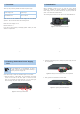
4. Wiring the DC Power Input
The 3-pin terminal block connector on the redundant power uses DC
power input. Please follow the steps below to insert the power wire.
Note
1. Before connecting the DC power wires, please
check whether your local DC power source is
stable.
2. The wire gauge for the power cable should be in
the range of 12 ~ 24 AWG.
3. The DC power input range is -36 ~ -72V DC.
1. Insert the positive DC power wire into the positive(+) contact
(left pin) and tighten the wire-clamp for preventing the DC power
wire from loosening.
2. Insert the negative DC power wire into the negative(-) contact
(middle pin) and tighten the wire-clamp for preventing the DC
power wire from loosening.
3. Insert the grounding power wire into the grounding(G) contact
(right pin) and tighten the wire-clamp for preventing the power
wire from loosening.
Figure 4-1 Power Pin Design of XGS-PWR150-DC
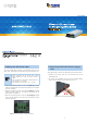
5. Removing Redundant Power Supply
Unit
Follow these steps to remove the redundant power from the switch:
1. Remove all DC power wires from the terminal block of the
XGS-PWR150-DC.
2. To remove the redundant power from the XGS-6350-24X4C,
loosen the thumbscrews on both sides and pull it out.
1
1
2
Figure 5-1 Removing the XGS-PWR150-DC