24 Ports + 1 slot Managed Ethernet Switch WSW-2401 User’s Manual
Trademarks Copyright PLANET Technology Corp. 2003. Contents subject to revision without prior notice. PLANET is a registered trademark of PLANET Technology Corp. to their respective owners. All other trademarks belong Disclaimer PLANET Technology does not warrant that the hardware will work properly in all environments and applications, and makes no warranty and representation, either implied or expressed, with respect to the quality, performance, merchantability, or fitness for a particular purpose.
TABLE OF CONTENTS CHAPTER 1 INTRODUCTION...................................................................................1 1.1 CHECKLIST ......................................................................................................................... 1 1.2 ABOUT THE SWITCH ............................................................................................................ 1 1.3 PRODUCT FEATURE .................................................................................................
3.7-3 TFTP Configuration ................................................................................................. 29 3.8 LOGOUT ........................................................................................................................... 30 CHAPTER 4 WEB MANAGEMENT.........................................................................31 4.1 LOGIN INTO SWITCH........................................................................................................... 31 4.
Chapter 1 Introduction 1.1 Checklist Thank you for purchasing Planet’s WSW-2401 Managed Ethernet Switches. Before continuing, please check the contents of your package for following parts: Ø WSW-2401 Managed Ethernet Switch Ø Power Cord Ø RS-232 cable Ø CD-ROM Ø Quick installation Guide Ø Rock-mounting blackest Note: if any of these pieces are missing or damage please contact your dialer immediately. 1.
1.3 Product Feature Ø 24 ports 10/100TX and 1 slot for option 1 or 2 ports 100FX module Ø Telnet, console and web manageable Ø 8K MAC address, auto-ageing Ø Support IGMP Ø Provide 8.8Gbps switch fabric Ø IEEE802.d Spanning tree protocol Ø IEEE802.1Q Tag VLAN with GVRP Ø IEEE802.3ad Link aggregation with LACP Ø Provide 24 auto-sensing 10/100Mbps Ethernet RJ-45 ports Ø IEEE802.1x user authentication with RADIUS client function Ø IEEE802.1p Priority, IEEE802.
Chapter 2 HARDWARE INSTALLATION This section is describes the hardware features and installation of 24 ports + 1 slot Managed Ethernet Switch. Before using WSW2401, read the user’s manual carefully. WSW2400 has four different modules for expansion: Ø WSW-1ST - 1port 100BaseFX Fast Ethernet Module (ST, MM, 2km) Ø WSW-1SC - 1port 100BaseFX Fast Ethernet Module (SC, MM, 2km) Ø WSW-2ST - 2 port 100BaseFX Fast Ethernet Module (SC, MM, 2km) Ø WSW-2SC - 2port 100BaseFX Fast Ethernet Module (ST, MM, 2km) 2.
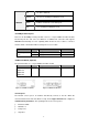
FDX/COL Off No device attached. Orange The port is operating in Full-duplex mode. Blinks Collision of Packets occurs in the port. Off The operating in half-duplex mode 10/100Mbps Ethernet ports There are 24 10/100Mbps R-J45 ports with 1 slot for 1 or 2-port 100Base-FX fiber module.
Ø Flow control: none After finished the setting, click OK. 2.2 Rear Panel The Rear Panel of the switch is indicates an AC 3 pronged power socket and Ventilation fan. This switch will work with AC in the range 100-240V AC, 50-60Hz. Figure 2-5 Rear Panel of WSW-2401 Power Receptacle For the compatibility with electric service in most of areas, WSW-2401’s power supply can automatically adjust line power in the range 100-240V AC, 50-60Hz.
Module installation The slot on the font panel is purposed for installing optional modules. Following steps is described how to install a module. 1. Power off the switch. 2. Removing the two screws on the faceplate of slot with a flat-head screwdriver. 3. Push the module gently into the slot along the slide tracks. 4. Ensuring that it firmly engages with the connector then tighten the screws to secure the module.
Chapter 3 Console and Telnet Management 3.1 connect To PC by RS-232 cable The RS-232 console port is an interface that directly connects to the PC. When the connection between the PC and switch is ready, run the Hyper Terminal and configure its communication parameters. The operating mode of the console port is: Ø Baud rate: 9600 Ø Data bits: 8 Ø Parity: none Ø Stop bits: 1 Ø Flow control: none After finished the setting, click OK. 3.2 Telnet To access the switch through Telnet 1.
3.3 Main Menu Control key describe: Tab/Backspace: Move the vernier to configure item. Enter: Select item. Space: Toggle selected item to next configure or change the value. Esc: to exit the current action There are five selections as follow. Ø Status and Counters: Show the status of the switch. Ø Switch Static Configuration: Configure the switch. Ø Protocol Related Configuration: Configure the protocol function.
3.4-1 Port Status In this function, it displays the status of each port. Select the or to display the previous page or next page. 3.4-2 Port Counters In this function is display current port counter information. Select to set all ports counter to 0. Select to get news information. 3.
Module. 3.5 Switch Configuration There are 9 main functions in Switch configuration, which is Administration configuration, Port configuration, Trunk Configuration, Port Mirroring Configuration, VLAN Configuration, Priority Configuration, MAC Address Configuration, Misc Configuration and Main Menu. There are more sub-functions under the main functions. 3.
3.5-1-1 Device Information You can configure the device information Ø Select the to modify the Name, Description, Location and Contact Ø After setup complete press ESC goes back to action menu Ø After configuration press to save configuration 3.5-1-2 IP Configuration Press the to modify the DHCP, IP Address, Subnet mask and Gateway Ø After setup complete press ESC goes back to action menu Ø Press to save the configuration 3.
12
3.5-1-4 Password Configuration Allow user to modify the password Ø Select the Ø Old password: enter the old password Ø New password: enter the new password Ø Enter again: re-enter the new password again Ø Pressto save the configuration 3.5-2 Port configuration In this function, user can setup every port status. Ø Select Ø Use TAB /Backspace key to move between items Ø State: The port can be set enable or disable mode.
3.5-3 Trunk Configuration You can configure port trunk group Ø Select Ø Use TAB key move to the port that you want to add as trunk group Ø Use Space key to mark the port Ø Use TAB key move to trunk# (eg turnk 1, trunk 2…etc) to change the trunk# value to Static or LACP Ø Press to save the configuration 3.5-4 Port Mirroring Configuration You can configure Port mirroring function Ø Select Ø Mirroring State: The default value is “disable”.
3.5-5 VLAN Configuration There are five sub-menus in VLAN Configuration, which is VLAN Configuration, Create a VLAN Group, Edit/Delete VLAN Group ,Group Sorted Mode and Previous Menu 3.5-5-1 VLAN configure You must enable VLAN mode in VLAN configure function before you start to configure VLAN. Ø Select Ø Select the VLAN mode through the Space key Ø Press Space key to choice 802.
3.5-5-2 Create VLAN Group Create VLAN Ø Select Ø Type a name for new VLAN Ø Use TAB key move to VLAN ID and give a new ID number Ø Choice different VLAN protocol through the Space key Ø Set Tagged, Untagged or no of each port Ø Press ESC and choice to save configuration 3.
3.5-5-4 Group Stored Mode You can select VLAN Groups sorted mode: 1) Name 2) VLAN ID Ø Select Ø Use Space key to select the sorted mode Ø Press to save to configuration 3.5-5-5 Previous Menu Return to previous menu 3.5-6 Priority Configuration In this function you can configure priority level to each port.
3.5-7 MAC Address Configuration There are three sub-menus in MAC Address Configuration, which is Static MAC Address, Filtering MAC Address and Previous Menu 3.5-7-1 Static MAC Address Ø Select to add a Static MAC Address Ø After setup complete press ESC goes back to action menu Ø Press to save the configuration 3.
3.5-7-3 Previous Menu Return to previous menu 3.5-8 Misc Configuration You can configure the switch parameter Ø MAC Address Ageing Time: MAC address table refresh time setting. The valid range is 0, 300~765 seconds. Default is 300 seconds Ø Broadcast Storm Filter mode: configure the broadcast storm filter mode. Use Space key to select the values. The valid threshold values are 5%, 10%, 15%, 20%, 25%, and N/A. Ø Max Bridge Transmit Delay Bound: Limit the packets queuing time in switch.
3.5-9 Main Menu Return to main menu 3.6 Protocol Related Configuration There are six main functions in Protocol Related Configuration, which is STP, SNMP, LACP, IGMP/GVRP, 802.1X Configuration and Previous Menu 3.
3.6-1-1 STP setup Provide enable or disable STP function Ø Select Ø Use key to choice option Ø After complete press to save the configuration 3.6-1-2 System Configuration In this function allow modifying the STP system configuration Ø Select to modify Spanning Tree Parameters Ø After modify complete Press ESC goes back to action menu Ø Press to save the configuration 3.6-1-3 Per Port Setting In this function allow edit per port STP configuration.
3.6-1-4 Previous Menu Return to previous menu 3.6-2 SNMP Configuration This sub-menu contains four items, which is System Options, Community Strings, Trap managers and Previous Menu 3.
3.6-2-2 Community Strings In this function allow add community name Ø Select “Add” to enter into “Add SNMP community” screen, then press Edit Ø After input the community name use TAB key to move to the Write access mode Ø Use the Space key to change the access mode Ø After setup complete press ESC goes back to action menu Ø Press to save the configuration 3.
3.6-3-1 Working Ports In this function allow to set LACP port state activity of each port Ø Select Ø Press Space key to enable or disable LACP support Ø After complete setup press ESC goes back to action menu Ø Press to save the configuration 3.
3.6-3-3 Group Status Display the LACP groups status 3.6-3-4 Previous Menu Return to previous menu 3.6-4 IGMP/GVRP Configuration In this function allow you to enable or disable IGMP/GVRP Ø Select Ø Use Space key to change value Ø After complete setup press ESC goes back to action menu Ø Press to save the configuration 3.6-5 802.1X Configuration This sub-menu contains five items, which is 802.1X Setup, System Configuration, Per Port Setting, Misc Configuration and Previous Menu.
3.6-5-1 802.1x Setup In this function allow you to enable IEEE802.1x Ø Select Ø Use Space key to enable or disable 802.1x Ø After complete setup press ESC goes back to action menu Ø Press to save the configuration Note: Please be sure the RADIUS server is correctly configured before turn on this option! Refer to Appendix B for the details about how to setup a RADIUS. 3.6-5-2 System Configuration In this function allow setup 802.
Note: Please check with the network administrator about the parameter settings, or the switch client may failed in getting connected due to the incorrect parameters. 3.6-5-3 Per Port Setting In this function allow you to change 802.1x authentication of each port Ø Select Ø Use Space” key change the state value.
3.6-5-5 Previous Menu Return to previous menu 3.7 System Reset Configuration This sub-menu contains four items, which is Factory Default, System Reboot, TFTP Configuration and Previous Menu 3.
3.7-2 System Reboot Provide restart switch 3.7-3 TFTP Configuration This sub-menu contains four items Update firmware, Restore configuration, backup configuration and Previous menu 3.
3.7-3-2 Restore Configuration In this function allow you to restore file from TFTP server Ø Select to input the TFTP Server IP and Restore file name Ø After complete setup press ESC goes back to action menu Ø Press to save the configuration 3.
Chapter 4 WEB MANAGEMENT WSW-2401 is support web management therefore in this section will introduce the configuration and functions of the web-based management. Before to use web management, please setup the IP Address with the console port (RS-232) and use this IP address to configure WSW-2401 through the web interface or modify your PC’s IP domain to the same with WSW-2401 then use the default IP address to remote configure WSW-2401 through the Web interface. 4.
4.2 Port Status This section is provide detail status of each port from WSW-2401 Ø Link: indicate the port status. UP means the device is connected to the port Down means the device is not connected to the port Ø Ø Ø Ø Ø Ø State: display the status of each port.
Ø Priority: display the priority status of each port Ø Security: display the port security is on or off Ø Config: display the current configuration of each port. Ø Actual: display the current state of each port on WGSD-1020. 4.3 Port Statistics This function is provides the detail statistics of each port. Press the Clear button to clean all counts. 4.4 Administrator This section contains management function on WSW-2401.
4.4-1 IP Configuration This section allows modify the DCHP Client, IP Address, Subnet mask and Gateway. After modify the DHCP client, IP Address, Subnet mask and Gateway, click Apply. Click System reboot. WSW-2401 will reboot to take effect for the new setting.
4.4-2 Switch Settings This section is provide basic information and allows modify the switch setting 4.4-2-1 Basic Ø System Name: the name of switch Ø System Location: the switch physical location.
4.4-2-2 Advanced There are two section includes in Advanced setting which is Disable MAC Address Aging out and Priority Queue Service After setup complete click Apply button. Disable MAC Address Aging out Ø Age-out Time: the number of seconds that an inactive MAC address remains in the Switch’s address table. The valid range is 300-765 seconds. The default value is 300 sec. Ø Max Bridge Transmit Delay Bound: limit the packets queuing time in switch. If enable, the packets queued exceed will be drop.
4.4-2-3 Misc Config Ø Collisions Retry Forever: disable is in half duplex. If happen collision will retry 48 times and then drop frame. Enable is in half duplex. If happen collision will retry forever Ø Hash Algorithm: CRC Hash or Direct Map for MAC address learning algorithm Ø IFG Compensation: Internal Packet Gap time compensation configure. Select to Enable or Disable Ø 802.1X Protocol: enable or disable 802.
4.4-4 Port Controls This section is introduces detail status of each port on WSW-2401 Ø State: user can enable or disable any port Ø Negotiation: user can set auto or force mode. Ø Speed: set speed of each port Ø Duplex: allow to set full or half duplex mode Ø Flow Control: provide on or off flow control function for full duplex Ø Back Pressure: provide on or off flow control function for half duplex Ø Bandwidth: allow user to set up rate control.
each port Ø Priority: allow to set high, low and disable priority function Ø Security: allow user to enable security function. When this function is enabling, the port will locked without permission of address learning. Ø After setup complete, click Apply button 4.4-5 Trunking This section display the detail status of trunking 4.4-5-1 Aggregator Setting Ø System priority: A value used to identify the active LACP.
4.4-5-2 Aggregator Information Provide the Aggregator Setting information 4.4-5-3 State Activity After you setup LACP Aggregator, you can configure port state activity Ø Active (enable):. The port automatically sends LACP protocol packets Ø Passive (not enable active): the port does not automatically sends LACP protocol packets and only respond when it receives LACP protocol packets from the opposite device.
4.4-6 Forwarding and Filtering WSW-2401 is support IP multicast and allows enable IGMP Protocol on Switch setting advantaged page from web interface. 4.4-6-1 IGMP Snooping Ø Select enable on IGMP Protocol Ø After setup complete click Apply button 4.
Ø In VLAN ID type a VLAN ID Ø Click Apply button to take effect Ø Use Delete button to delete unwanted MAC Address 4.4-6-3 MAC Filtering This section allow user to block unwanted traffic Ø In MAC Address column enter MAC Address that want to filter Ø In VLAN ID type a VLAN ID Ø Click Add button Ø Use Delete button to delete unwanted MAC Address 4.4-7 VLAN Configuration A Virtual LAN (VLAN) is a logical network grouping that limits the broadcast domain.
Ø Select 802.
4.4-7-2 Port-based VLAN Ø Select 802.1Q mode from VLAN Operation Mode Ø Click Add button to create new VLAN group Ø Type a name for new VLAN and VLAN ID Ø From the available ports box, select ports to add to the Switch and click Add Ø Click Apply button after compete setup 4.
port Ø Ingress Filtering: Ingress filtering lets frames belonging to a specific VLAN to be forwarded if the port belongs to that VLAN. The user allow to enable or disable this function Ø Acceptable Frame Type: allow user to select different frame type which is All or Tag only Ø Click Apply after setup complete 4.4-8 Spanning Tree The Spanning-Tree Protocol (STP) is a standardized method (IEEE 802.1d) for avoiding loops in switched networks.
4.4-8-2 Per Port configuration Ø You can view spanning tree status about switch Ø Select the port in Port column. Ø Assign the Path Cost. The value range is from 1 to 65535. Ø Assign the port priority value. The value range is from 0 to 255. The lowest value has higher priority. Ø Click Apply button 4.4-9 Port Mirroring Port Mirroring is a method for monitor traffic in WSW-2401 network. Traffic through ports can be monitored by one specific port.
Ø Port Mirroring State: provide disable, RX, TX and Both port Mirroring function Ø Analysis Port: allow seeing all monitor port traffic. You can connect mirror port to LAN analyzer or netxray Ø Monitor Port: the ports that you want to monitor. 4.4-10 SNMP Management Allow to management the WSW-2401 through the Simple Network Management Protocol (SNMP).
System Options Ø Name: enter the system name for this switch Ø Location: enter the location for this switch Ø Contact: enter the name of contact person or company Ø Click Apply button after finish setup Community strings Ø String: fill the name of string Ø RO/ Read Only:. Enable requests accompanied by this string to display MIB-object information Ø RW/ Ready Write: Enable requests accompanied by this string to display MIB-object information and set MIB objects.
Ø Input the new user name. Ø Input the new password. Ø Re-input the new password. Ø Click “Apply” button to modify 4.4-12 802.1x configuration This section you can enable and configure the parameters of 802.1x function 4.4-12-1 System Configuration .
Radius Server Ø Shared Key: set an encryption key for use during authentication sessions with the specified radius server. Ø NAS, Identifier: set the identifier for the radius client. Ø Click Apply button 4.4-12-2 Per Port Configuration Ø Select port column Ø Select the state of port. There are four states which is disable, Authorized, Reject and Accept Ø Click Apply button 4.
Ø Quiet Period: used to define periods of time during which it will not attempt to acquire a supplicant(Default time is 60 seconds). Ø Tx Period: used to determine when an EAPOL PDU is to be transmitted(Default value is 30 seconds). Ø Supplicant Timeout: used to determine timeout conditions in the exchanges between the supplicant and authentication server(Default value is 30 seconds).
4.4-14 Configuration Backup This section allow user to Restore and Backup into WSW-2401 4.4-14-1 TFTP Restore Configuration Ø TFTP Server IP Address: enter the IP address of TFTP server Ø Restore File Name: enter the file name that want to restore Ø Click Apply button 4.
4.4-15 Factory Default This function provides reset the Switch to factory default mode 4.
Chapter 5 TROUBLESHOOTING This chapter contains some information to help you to solve most command problems on the WSW-2401 The LED is not lit Solution Check the cable connection Port cannot communication to other stations located on other port Solution Please check VLAN, and port Trunk function, which may indicate this kind of problem Bad Performance Solution Please check the duplex status on switch; if the switch is set full duplex and the partner is set half duplex then performance poor will occur.
Chapter 6 TECHNICAL SPECIFICATION Model Ports Dimensions Weight Power Requirement Switch architecture MAC Address table Memory Auto-MDI/MDI-X Flow Control EMI Safety Standards WSW2401 24 10/100Base-TX RJ-45 Auto-MDI/MDI-X ports 1 open slot 1 RS-232 DB-9 male 440mm(W)*225mm(D)*44.5mm(H) 1U height 3 kg 100-240 VAC 50-60Hz Store-and-forward, Back-plane 8.8 Gbps 8K entries, auto learning/ageing 384KB for packet buffer Support on all RJ-45 ports Back pressure for half duplex, IEEE 802.
APPENDIX A A.1 Switch‘s RJ-45 Pin Assignments 1000Mbps, 1000Base T Contact MDI MDI-X 1 BI_DA+ BI_DB+ 2 BI_DA- BI_DB- 3 BI_DB+ BI_DA+ 4 BI_DC+ BI_DD+ 5 BI_DC- BI_DD- 6 BI_DB- BI_DA- 7 BI_DD+ BI_DC+ 8 BI_DD- BI_DC- Implicit implementation of the crossover function within a twisted-pair cable, or at a wiring panel, while not expressly forbidden, is beyond the scope of this standard. A.2 10/100Mbps, 10/100Base-TX Contact MDI MDI-X 1 1 3 2 2 6 3 3 1 6 6 2 A.
APPENDIX B WSW-2401 is with IEEE802.1x authentication capability, before you turn on the 802.1x function, the following sections shows the required environment for 802.1. Section B.1 describes the infrastructure of the IEEE802.1x Section B.2 describes how to setup the IEEE802.1x server base on Windows 2000 server. Section B.3. shows how to setup and enable the IEEE802.1x client in your workstation, example on Windows XP. B.1 802.1X Infrastructure 1. An 802.
3. Click on “Add/Remove Windows components”. 4. Check “Certificate Services”, and click “Next” to continue. 5.Select “Enterprise root CA”, and click “Next” to continue. 6. Enter the information that you want for your Certificate Service, and click “Next” to continue. 7. Go to Start > Program > Administrative Tools > Certificate Authority. 8. Right-click on the “Policy Setting”, select “new”. 9. Select “Certificate to Issue”.
10. Select “Authenticated Session” and “Smartcard Logon” by holding down to the Ctrl key, and click “OK” to continue. 11. Go to Start > Program > Administrative Tools > Active Directory Users and Computers. 12. Right-click on domain, and select ”Properties” to continue.
13. Select “Group Policy” tab and click “Properties” to continue. 14. Go to “Computer Configuration” > “Security Settings” > “Public Key Policies” 15. Right-click “Automatic Certificate Request Setting”, and select “New” 16. Click “Automatic Certificate Request ..
17. The Automatic Certificate Request Setup Wizard will guide you through the Automatic Certificate Request setup, simply click “Next” through to the last step. 18. Click “Finish” to complete the Automatic Certificate Request Setup 19. Go to Start > Run, and type “command” and click “Enter” to open Command Prompt. 20.
Adding Internet Authentication Service 21. Go to Start > Control Panel > Add or Remove Programs. 22. Select “Add/Remove Windows Components” from the panel on the left. 23. Select “Internet Authentication Service”, and click “OK” to install Setting Internet Authentication Service 24. Go to Start > Program > Administrative Tools > Internet Authentication Service. 25.
26. Enter the IP address of WSW-2401 in the Client address text field, a memorable name for WSW-2401 in the Client-Vendor text field, the access password used by WSW-2401 in the Shared secret text field. Re-type the password in the Confirmed shared secret text field. 27. Click “Finish”. 28.
29. Select “New Remote Access Policy” 30. Select “Day-And-Time-Restriction”, and click “Add” to continue. 31. Unless you want to specify the active duration for 802.1X authentication, click “OK” to accept for having 802.1x authentication enabled at all times.
32. Select “Grant remote access permission”, and click “Next” to continue. 33. Click “Edit Profile”.
For MD5 Authentication Setup (Steps 34 ~ 35) 34. Select “Authentication” Tab. 35. Enable “Extensible Authentication Protocol”. Select “MD5-Challenge” and enable “Encrypted Authentication (CHAP)” for MD5 authentication. Click “OK” 36. Select “Internet Authentication Service (Local)”, click on “Action” from top panel.
click “Register Service in Active Directory”. 37. Go to Start > Program > Administrative Tools > Active Directory Users and Computers. 38. Right click on the domain, and select “Properties” 39.
40. Go to “Computer Configuration” > “Windows Settings” > “Security Settings” > “Account Policies” > “Password Policies”. Double click on “Store password using reversible encryption for all users in the domain”.
41. Click “Define this policy setting”, select “Enabled”, and click “OK” to continue 42. Go to Start > Program > Administrative Tools > Active Directory Users and Computers. 43. Go to Users. Right-click on the user that you are granting access, and select “Properties”. 44. Go to “Account” tab, and enable “Store password using reversible encryption”. 45.
46. Go to the “Dial-in” tab, and check “Allow access” option for Remote Access Permission and “No Call-back” for Callback Options. Then click “OK”.
B.3 Switch client setup Windows XP is originally 802.1X support. As to other operating systems (windows 98SE, ME, 2000), an 802.1X client utility is needed. The following procedures show how to configure 802.1X Authentication in Windows XP B.3.1 EAP-MD5 Authentication 1. Go to Start > Control Panel, double-click on “Network Connections”. 2. Right-click on the Network Connection that connect with WSW-2401. 3. Click “Properties” to open up the Properties setting window.
4. Select on the “Authentication” tab. 5. Select “Enable network access control using IEEE 802.1X” to enable 802.1x authentication. 6 Select “MD-5 Challenge” from the drop-down list box for EAP type.
7 Click “OK” 8 When Switch client has associated with WSW-2401, a user authentication notice appears in system tray. Click on the notice to continue and get the authentication from your Windows 2000 server.