24-Port 10/100Mbps with PoE + 2G TP/SFP Combo Managed Ethernet Switch WGSW-2620PV User's Manual
Trademarks Copyright © PLANET Technology Corp. 2005. Contents subject to which revision without prior notice. PLANET is a registered trademark of PLANET Technology Corp. All other trademarks belong to their respective owners.
Table of Contents 1. INTRODUCTION ................................................................................................................... 5 1.1 Packet Contents .............................................................................................................. 5 1.2 How to Use This Manual ................................................................................................. 5 1.3 Product Feature.................................................................................
5. TROUBLESHOOTING ...................................................................................................... 128 5.1 Incorrect connections .................................................................................................. 128 5.2 Diagnosing LED Indicators.......................................................................................... 128 5.3 Diagnosing POE problems.......................................................................................... 129 6.
1. INTRODUCTION 1.1 Packet Contents Check the contents of your package for following parts: ▫ Fast Ethernet PoE Switch x1 ▫ CD-ROM user's manual x1 ▫ Quick installation guide x1 ▫ 19" rack mounting kit x1 ▫ Power cord x1 ▫ Rubber feet x 4 If any of these are missing or damaged, please contact your dealer immediately, if possible, retain the carton including the original packing material, and use them against to repack the product in case there is a need to return it to us for repair. 1.
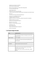
Gigabit fiber, 802.3af power over Ethernet ▫ High back-plane bandwidth 8.8Gbps ▫ IGMP snooping and IGMP Query mode for Multi-media application ▫ Port mirror and bandwidth control ▫ Supports GVRP function ▫ End point insert mode remote power feeding ▫ Provides extra DC 48V input with redundant function and management power status through RS-232 port ▫ On line extra power supply testing through RS-232 port ▫ Management by Web/SNMP/Telnet/Console ▫ Port Based VLAN /802.1Q Tag VLAN ▫ IEEE802.
100FX module (module)): Link/Activity, Full duplex Remote power feeding End-point insert type and compatible with IEEE802.3af Per port feeding power: 15.4Watts (maximum) Power Embedded AC power supply: AC 90~240V, 2.5A, 50/60Hz, 200W Extra power input: DC48V Operating environment 0℃~40℃, 10%~95%RH Storage environment -40℃~70℃, 95% RH Dimension 440mm(W) x 280mm(D) x 44mm(H) EMI FCC Class A, CE Safety UL, cUL, CE/EN60950 Standard Compliance IEEE802.3 10BASE-T IEEE802.
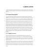
2. INSTALLATION This section describes the functionalities of the Switch's components and guides how to install it on the desktop or shelf. Basic knowledge of networking is assumed. Please read this chapter completely before continuing. 2.1 Product Description The PLANET WGSW-2620PV PoE Switch features Power-over-Ethernet (PoE), which optimizes the installation and power management of network devices such as wireless access points (AP), Voice over IP (VoIP) phones, and security video cameras.
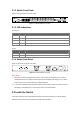
2.1.2 Switch Front Panel Figure 2-1 shows the front panel of the switch. Figure 2-1 WGSW-2620PV front panel. 2.1.3 LED Indications Network/PoE: LED Color Function PWR Green Lights to indicate that the Switch is powered on. PoE Green Lights to indicate the port is providing 48VDC in-line power. LNK/ACT Green Lights to indicate the link through that port is successfully established. FDX/COL Green Blink to indicate that the switch is actively sending or receiving data over that port.
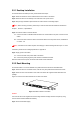
2.2.1 Desktop Installation To install the Switch on desktop or shelf, please follows these steps: Step1: Attach the rubber feet to the recessed areas on the bottom of the switch. Step2: Place the switch on the desktop or the shelf near an AC power source. Step3: Keep enough ventilation space between the switch and the surrounding objects. "Note: When choosing a location, please keep in mind the environmental restrictions discussed in Chapter 1, Section 4, in Specification.
Step4: Follow the same steps to attach the second bracket to the opposite side. Step5: After the brackets are attached to the Switch, use suitable screws to securely attach the brackets to the rack, as shown in Figure 2-6 Figure 2-6 Mounting the Switch in a Rack Step6: Proceeds with the steps 4 and steps 5 of session 2.2.1 Desktop Installation to connect the network cabling and supply power to the switch.
3. CONSOLE MANAGEMENT 3.1 Connecting to the Switch The console port is a female DB-9 connector that enables a connection to a PC or terminal for monitoring and configuring the Switch. Use the supplied RS-232 cable with a male DB-9 connector to connect a terminal or PC to the Console port. The Console configuration (out of band) allows you to set Switch for remote terminal as if the console terminal were directly connected to it. 3.
bring out the login prompt. Key in the “admin“(default value) for the both User name and Password (use Enter key to switch), then press Enter key and the Main Menu of console management appears. Please see below figure for login screen. Console login screen 3.3 CLI Management The system supports two types of console management - CLI command and Menu selection. After you login to the system, you will see a command prompt. To enter CLI management interface, enter "enable" command.
information. The privileged command is advance mode Privileged Enter the enable command while in EXEC switch# user EXEC mode. Enter disable to Privileged this mode to exit. • Display advance function status • Save configures Global Configuratio n Enter the configure To exit to Use this mode to command while in switch privileged EXEC configure parameters that privileged EXEC (config)# mode, enter exit apply to your switch as a or end whole.
3.3.2 Commands Set List 3.3.2.
Global default configuration Restore to default default mode Global username [user-name] configuration mode Global password [password] configuration mode Switch (config)# Changes a login username. Switch (config)# (maximum 10 words) username xxxxxx Switch (config)# Specifies a password password xxxxxx (maximum 10 words) Switch> show system info Name: switch1 show system location: lab User EXEC Show system information info Description: layer2 switch Contact: somewhere Serial NO: 1.
Switch# show show accounting Privileged Show username & EXEC password accounting Username: admin Password: admin Switch> show version show version User EXEC Use the show version user Firmware version: EXEC command to display 1.0 version information for the Hardware version: hardware and firmware. 3.0 Kernel version: 1.
Switch (config)# Use the module Ethernet interface interface configuration moduleEthernet command 1/1 Use the duplex Switch (config)# configuration command interface to specify the duplex mode of operation for Auto Fast Interface duplex [full | half| auto] fastEthernet 0/1 Switch (config-if)# duplex full Ethernet.
for speed 100) (The 1000Base-FX module only supported for speed 1000 & auto) Use the flow control configuration command Switch (config)# on Ethernet ports to flowcontrol on or no flowcontrol Interface control traffic rates during configuratio congestion. interface On n mode fastEthernet 0/1 Switch (config-if)# Use the no form of this flowcontrol on command to disable security on the port.
Set bandwidth in or out Switch (config)# rate. The value rage is Bandwidth [in | out] [value] Interface (0~999), and zero of the configuratio value is disable interface Disable n mode fastEthernet 0/1 Switch (config-if)# (The module can’t be bandwidth hi 50 setting) Use the state interface State [Enable | Disable] configuration command Switch (config)# Interface to specify the state mode interface configuratio of operation for Ethernet n mode ports.
Switch (config)# interface Interface show interface accounting configuratio n mode show interface statistic fastEthernet 0/1 counter Switch (config-if)# show interface accounting Switch (config)# Interface show bandwidth configuratio n mode interface Display the bandwidth of fastEthernet 0/1 the values Switch (config-if)# show bandwidth 3.3.2.
LACP: port group Switch (config)# [group-number] port group 1 1-4 [port-list] lacp [on | off] workp [work ports] lacp on Add trunking group. workp 2 Global configuratio Use the no form of this n mode command to delete Trunk without trunking group.
vlanmode [disable| VLAN portbase| 802.1q | database gvrp] mode To set switch VLAN mode .Use the no form of this command to restore Disable Switch (vlan)# vlanmode 802.1q to default.
[port ID]: port members 1~9 VLAN vlan [group name] delete [port ID] database mode Remove the port from its port group. Switch(vlan )# vlan v2 delete 5 Switch (vlan)# no no vlan [Group name] or [VLAN ID] VLAN database vlan v2 Delete 802.
IBM SNA-ibm X.75 internet-x75 X.
IBM SNA-ibm X.75 internet-x75 X.
Switch VLAN protocol VLAN [Groupname] add [portNumber] database mode Set the port of some port group tagged or untagged (vlan)# vlan protocol v2 add 5 [tagged | untagged] tagged VLAN protocol VLAN [Groupname] delete database [portNumber] mode Switch Remove the port from its port (vlan)# vlan group.
Port Vid: 2 Ingress 1 Filter: Disable Ingress 2 Filter: Enable 3.3.2.5 Spanning Tree Commands Set Commands Command Level Description Defaults Example Switch> show spanning-tree System: Priority: 32768 Max Age: 20 Hello Time: 2 Display a show spanning-tree User EXEC summary of the mode spanning-tree states.
Use the spanning-tree global configuration spanning-tree [on / Global command to off] or no configuratio enable Spanning spanning-tree n mode Tree Protocol Disable Switch (config)# spanning-tree on (STP). Use the no form of the command to restore to default Use the spanning-tree max-age global configuration Global spanning-tree priority [number] configuratio command to change the priority.
receive a bridge protocol data unit (BPDU) message from the root switch within this interval, it recomputes the Spanning Tree Protocol (STP) topology. Use the no form of this command to return to the default interval. Use the spanning-tree hello-time global configuration command to specify the interval spanning-tree Global hello-time configuratio [seconds] n mode Switch (config)# between hello 2 sec. bridge protocol spanning-tree hello-time 3 data units (BPDUs).
Protocol (STP) – 10 calculations. In the event of a loop, spanning tree considers the path cost when selecting an interface to place into the forwarding state. Use the no form of this command to return to the default value. Use the spanning-tree forward-time global configuration command to set the forwarding-time for the specified spanning-tree Global forward-time configuratio [seconds] n mode spanning-tree instances.
Use the spanning-tree port-priority interface configuration stp-path-priority [Port Priority] command to Switch (config)# Interface configure a port interface fastEthernet configuratio priority that is used n mode when two switches 128 0/2 Switch (config-if)# tie for position as stp-path-priority 127 the root switch. Use the no form of this command to return to the default value. 3.3.2.
Global qos level [priority] enable no qos level [priority] configuratio 0~3 LOW [Priority] 0~7 n mode 4~7 HI Global 0~3 LOW configuratio [Priority] 0~7 4~7 HI n mode Switch (config)# qos level 2,3 enable Switch (config)# no qos level 0-7 WRR: Switch (config)# qos queuepolicy wrr hi 7 [Policy]:fcfs: first in low 1 and first out wrr: weight round qos queuepolicy Global [Policy] hi [Priority] configuratio low [Priority] n mode WRR robin First Come First Served: Hi 2 sp: all high before
Switch (config)# show qos show qos Privileged low-priority-delay-b EXEC ound mode Show low priority low-priority-delay-boun delay board. d Qos low priority delay bound: 1 Switch (config)# show Privileged show qos policy EXEC qos policy Show qos policy mode Qos Mode: WRR Switch (config)# show Privileged show qos bridge-delay-bound EXEC mode Show bridge delay qos bound bridge-delay-bound bridge-delay-bound 5 3.3.2.
Port 224.1.1.1 10 1,2,6 3.3.2.
command to 004063112233 vlanid 10 remove static entries from the MAC address table. Use the no Switch (config)# mac-address-table interface fastEthernet Interface privileged EXEC 0/2 configuratio command to Switch (config-if)# no n mode delete entries from no mac-address-table [static | filter] hwaddr [MAC address] vlanid mac-address-table the MAC address [VLAN-ID] static hwaddr table.
snmp Global system-location configuratio [SystemLocation] n mode snmp Global system-contact configuratio [SystemContact] n mode Set Snmp agent system location Set Snmp agent system contact N/A Switch (config)# snmp system-location lab N/A Switch (config)# snmp system-contact where snmp community-strings Add snmp [Community] community string.
Analyzer (SPAN) no port monitor monitor both 3 port monitoring on a port. Use the no form of this command to return the port to its default value.
3.3.2.11 802.1x Commands Set Command Commands Description Defaults Example Level Display a User EXEC show 8021x mode summary of the 802.1x properties N/A Switch> show 8021x and also the port sates. Use the 802.1x global configuration 8021x [on | off] Global command to configuratio enable 802.1x n mode protocols. Use the Disable Switch (config)# 8021x on no form of the command to restore to default Use the 802.
Use the 802.1x system sharekey global 8021x system configuration sharekey command to [Sharekey] Or Global change the shared configuratio key value. Switch (config)# 8021x N/A system sharekey 123456 n mode no 8021x system Use the no form of sharekey this command to return to the default interval.
this command to return to the default interval. Use the 802.1x misc TX period global configuration 8021x misc txperiod [TXPeriod value] Or Global configuratio command to set the TX period. N/A n mode no 8021x txperiod Switch (config)# 8021x misc txperiod 5 Use the no form of this command to return to the default value. Set the period of 8021x misc supptimeout [SEC] Or Global configuratio n mode time the switch wait for a supplicant no 8021x response to an supptimeout EAP request.
authentication maxrequest session ends. 8021x misc reauthperiod [SEC] Or Set the period of Global time after which configuratio clients connected n mode must be no 8021x N/A Switch(config)# 8021x misc reauthperiod 20 re-authenticated.. reauthperiod Use the 802.1x port state interface configuration command to set the state of the selected port.
state. 3.3.2.12 TFTP Commands Set Command Commands Description Defaults Example Level Switch (config)# copy copy flash:config.text Global tftp [TFTP IP configuration address] [file mode flash:config.text tftp Backup configure file command >192.168.0.10 >backup.dat name] Switch(config)# tftp:config.text flash [TFTP IP address] Global Restore configuration configure file mode command Tftp:config.text flash >192.168.0.10 [file name] >restore.
UPS status. Input Output Voltage like web information Switch (ups)# info Info UPS mode Company Name :xxx Show UPS information Model :xxx Version :xxx UPS will perform test 10 UPS mode Switch (ups)# test 10 the self-test for 10 test OK seconds. 3.3.2.14 POE Commands Set Comma Commands Description Defaults Example nd Level Switch (poe)#status status POE mode Show POE information like web information Enabling or setpm POE mode disabling the power management.
Enabling or disabling total power output limit. When is enabling, setlimit POE mode the total power output limit will Switch (poe)# setlimit Set Total Power Limit [123]=100 follow the value that set in power limit max. setps1 POE mode Setup Power Supply 1 Limit Enabling or portebl POE mode disabling the port POE inject function.
Switch (poe)# portpri Set Port [1~8]=1 Set port priority for portpri POE mode the power supply management. Set Port 19847000 Priority (1:Critical, 2:High, 3:Low) Old=[0], New=2 Switch (poe)# portpplm Set Port [1~8]=1 Set Port portplm POE mode Port Power Limit Max Setting 1 Power Limit Max Old=[15400],New=20000 Set Port 1 Power Limit Max 20000 save POE mode restore POE mode Store current configure Restore to default Switch (poe)#save Switch (poe)#restore 3.
。 System Reset Configuration: Restart the system or reset switch to default configuration. 。 UPS menu: configure the UPS function. 。 POE menu: configure the POE function. 。 Save Configuration: save the current configuration into the system memory. 。 Logout: Exit the menu line program. Main Menu Line Interface 。 Control Key description: The control keys provided in all menus: ¾ Tab/Backspace: Move the vernier to configure item. ¾ Enter: Select item.
Status and Counters main configuration interface 3.4.1.1 Port Status It displays status of each port. Select the action to display previous page. And, select the action to display next page. 。 。 Type: display port connection speed. Link: display port statuses link status. When the port is connecting with the device and work normally, the link status is “UP”. Opposite is “Down”. 。 。 。 。 。 。 State: The port current status. 。 。 Priority: display the port priority status.
Port status display interface 3.4.1.2 Port Counters It displays the current port counter information. Select the to get newest counter information. Select to set all ports counter to 0. Port counter information interface 3.4.1.3 System Information It displays the system parameter. 。 System Name: the name of device.
。 System Location: where the device is located. 。 System Description: the name of device type. 。 Firmware Version: the switch's firmware version. 。 Hardware Version: the switch's Hardware version. 。 Kernel Version: the system kernel software version. 。 MAC Address: The unique hardware address assigned by manufacturer. 。 Module Information: display information of installed module. System Information interface 3.4.
Switch Configuration interface 3.4.2.1 Administration Configuration In Administration Configuration, you can configuration system parameter, IP, login username, password, and SNTP configuration. Administration Configuration main interface 3.4.2.1.1 Device Information You can configure the device information. Select action to configure. 1. Name: assign the name for the switch.
2. Description: a short description for the switch. 3. Location: the switch location, ex: Taipei. 4. Contact: the contact person or information. 5. Select action to apply the configuration. Device Information interface 3.4.2.1.2 IP Configuration You can configure the IP for this switch. The system has the default IP address. You can re-configure or use the default value. 1. Select the 2. DHCP Client: "Enable" is to get IP from DHCP server. "Disable" is opposite.
IP Configuration interface 3. 4.2.1.3 User Name Configuration You can change the console and web management login user name. 1. Select the 2. Enter the new user name 3. Select the User Name Configuration interface 3.4.2.1.4 Password Configuration You can change the console and web management login password.
1. Select the 2. Old Password: enter the old password. 3. New Password: enter the new password. 4. Enter Again: reenter the new password for confirmation. 5. Select the Password Configuration interface 3.4.1.4.5 SNTP Configuration You can configure the SNTP (Simple Network Time Protocol) settings. The SNTP allows you to synchronize switch clocks in the Internet. 。 SNTP Client: enable or disable SNTP function to get the time from the SNTP server.
SNTP Configuration Interface 3.4.1.4.6 Syslog Client Configuration You can configure the switch as the system log client that can view the system log information that from the system log server that you have assigned. 1. Select 2. Syslog Client: enabling or disabling the system log client function. "Enable" can view the system log information from the assigned system log server. 3. Server IP: assigned the system log server IP. 4. Select to apply the configuration.
3.4.2 Port Configuration You can set up every port status. 1. Select 2. Use "Tab/Backspace" key to move between items. 3. State: Current port status. The port can be set to disable or enable mode. If the port setting is disable then will not receive or transmit any packet. 4. Negotiation: set auto negotiation function of port. 5. Speed/Duplex: set the port link speed and duplex mode. 6. FC: enable or disable Flow control function (Flow control for full duplex link mode). 7.
5. Apply the configuration by selecting . Trunk Configuration interface 3.4.4 Port Mirroring Configuration The port mirroring is a method for monitor traffic of switched networks. The specific port can monitor traffic through the mirror ports. The monitored ports in or out traffic will be duplicated into monitoring port. 1. Select the 2. Mirroring State: select the port-mirroring mode. The default value is "Disable". To start port mirroring, you must select one of port mirroring mode.
Port Mirroring interface 3. Analysis port: Set the destination port of mirroring packet. All of the packets of mirroring port will be duplicated and sent to Analysis port. 4. Port State: Select the ports that want to be mirrored. 5. Use "Space" key to mark the mirroring port can. 6. Select the . Port Mirroring interface 3.4.5 VLAN Configuration You can configure VLAN group in VLAN Configuration.
mode: VLAN Configuration, Create a VLAN Group, Edit/Delete VLAN Group and Group Sorted Mode. Follow the below description to configure VLAN. VLAN Configuration Main interface 3.4.5.1 VLAN Configure Before starting to configure VLAN, you must select the VLAN mode in VLAN Configure function. Otherwise, user cannot create any new VLAN. 1. Select the . 2. Select the VLAN mode by using "Tab" key. There are two VLAN modes: PortBase mode and 802.1Q mode. When select the 802.
VLAN Configure interface 3.4.5.2 Create VLAN Group Create Port-Based VLAN 1. Select . 2. VLAN Name: Type a name for the new VLAN, ex: VLAN01. 3. Group ID: Type the VLAN group ID. 4. Member: Press "Space" key to change the member value. There are two types to selected: 。 Member: the port is a member port. 。 NO: it means that port is NOT a member port. 5. Press "ESC" key to go back action menu line. 6. Select to apply the configuration.
Create VLAN Group: PortBase interface Create 802.1Q VLAN 1. Enable security VLAN setting: select to enable or disable security VLAN group. When you select to enable security VLAN group, only the members in this VLAN group can access to the switch. The steps of setting security VLAN refer to the following step 2~ 8. After you have configured the security VLAN group, you can continue to create other VLAN groups.
3. VLAN Name: Type a name for the new VLAN, ex: VLAN01. 4. VLAN ID: Type a VID. The default is 1. There are 256 VLAN groups to provided configure. 5. Protocol VLAN: Press "Space" key to choose protocols type. 6. Member: Press "Space" key to change the member value. 。 Untagged: this port is the member port of this VLAN group and outgoing frames are NO VLAN-Tagged frames. 。 Tagged: this port is the member port of this VLAN group and outgoing frames are VLAN-Tagged frames.
1. The VLAN Name and VLAN ID cannot modify. 2. In 802.1Q VLAN mode, the default VLAN can't be deleting. 3. In Port Base VLAN mode, there is no default VLAN. Edit/Delete a VLAN Group interface Group Sorted Mode You can select VLAN groups sorted mode: (1) Name (2) VLAN ID. In the Edit/Delete a VLAN group page will display the result. 1. Select 2. Use "Space" key to select the sort mode. 3.
Group Sorted Mode interface 3.4.6 Priority Configuration You can configure port priority level. There are 0~7-priority level can map to high or low queue. 1. Select . 2. Press "Space" key to select the priority level mapping to high or low queue. 3. Qos Mode: User can select the ratio of high priority packets and low priority packets. 。 First Come first service: the switch will process the packet that is coming first.
3.4.7 MAC Address Configuration When you add a static MAC address, it remains in the switch's address table, regardless of whether the device is physically connected to the switch. This saves the switch from having to re-learn a device's MAC address when the disconnected or powered-off device is active on the network again. You can add / modify / delete a static MAC address. MAC Address Configuration interface 3.4.7.
Add Static MAC Address interface Edit static MAC address 1. Press . 2. Choose the MAC address that you want to modify and then press "Enter". 3. Press key to modify. 4. Press "ESC" to go back action menu line. 5. Select to apply all configure value. Delete static MAC address 1. Press key. 2. Choose the MAC address that you want to delete and then press "Enter". 3. When pressing "Enter" will complete deletion. 3.4.7.
Filtering MAC Address interface Add the Filtering MAC Address 1. Select --> key to add the static MAC address. 2. MAC Address: Enter the MAC address that you want to filter. 3. Press "ESC" to go back action menu line. 4. Select to apply all configure value. Add Filtering MAC Address interface Edit Filtering MAC address 1. Press key to modify a static Filtering address. 2. Choose the MAC address that you want to modify and then press "Enter".
3. Select key to modify. 4. Press "ESC" to go back action menu line 5. Select to apply all configure value. Delete Filtering MAC address 1. Press to delete a Filtering MAC address. 2. Choose the MAC address that you want to delete and then press "Enter". 3.4.7.3 Misc Configuration You can configure the switch parameters. MAC Address Ageing Time: MAC address table refresh time setting.
Misc Configuration interface 3.4.8 Protocol Related Configuration You can configure Spanning Tree Protocol, SNMP, LACP, IGMP/GVRP, and 802.1x in Protocol Relate Configuration section. Protocol Relate Configuration interface 3.4.8.
loops in the network. STP Configuration interface 3.4.8.1.1 STP Setup You must enable Spanning Tree function before configuration. 1. Select 2. Use “Space” key to select the option. 3. Select .
3.4.8.1.2 System Configuration You can configure the STP system parameter after enable the STP function. You can view spanning tree informationa about the Root Bridge on the left. 1. Select 2. Priority: assign path priority number. 3. Max Age: the maximum path age 4. Hello Time: the time that controls switch sends out the BPDU packet to check STP current status. 5. Forward Delay Time: forward delay time. 6. Select . STP System Configuration interface 3.4.8.1.3 Per Port Setting 1.
Per Port Setting interface 3.4.8.2 SNMP To define management stations as trap managers and to enter SNMP community strings. You can also define a name, location, and contact person for the switch. SNMP Configuration interface 3.4.8.2.1 SNMP System Options 1. Press . 2. Name: assign a name for the switch. 3. Contact: Type the name of contact person or organization.
4. Location: Type the location of the switch. 5. Press “ESC” goes back action menu line. 6. Press to apply configuration value. SNMP System Options interface 3.4.8.2.2 Community Strings Add Community Strings 1. Select -> . 2. Community Name: type the name of community strings. 3. Write Access: enable the rights is read only or read/write. 。 Read only: Read only, enables requests accompanied by this string to display MIB-object information.
Add Community Strings interface Edit SNMP Community 1. Select 2. Choose the item that you want to modify and then press “Enter”. 3. Community Name: type the new name. 4. Write Access: Press “Space” key to change the right. 5. Select . Delete SNMP Community string 1. Select . 2. Choose the community string that you want to delete and then press “Enter”. 3. When pressing “Enter” will complete deletion. 3.4.8.2.
Trap Managers interface Add the trap manager 1. Select -> to add the trap manager. 2. IP: type the IP address. 3. Community Name: type the community name. 4. Press “ESC” go back to actions menu line 5. Select to apply all configure. Add Trap Manager interface Delete Trap Manager 1.
2. Choose the trap manager that you want to delete and then press “Enter”. 3. When pressing “Enter” will complete deletion. 3.4.8.
LACP Working Ports configuration interface 3.4.8.3.2 LACP State Activity 1. Select 2. Use “Space” key to select the Port State Activity. 。 Active: The port automatically sends LACP protocol packets. 。 Passive: The port does not automatically send LACP protocol packets, and responds only if it receives LACP protocol packets from the opposite device. 3. Select .
3.4.8.3.3 LACP Group Status When you are setting trunk group, you can see the relation information in here. LACP Group State interface 3.4.8.4 IGMP/GVRP Configuration You can enable or disable the IGMP/GVRP (GARP VLAN Registration Protocol). 1. Select 2. Use “Space” key to change the value 3.
3.4.8.5 802.1x Configuration You can configure 802.1x relate settings. 802.1x Configuration interface 3.4.8.5.1 802.1x Setup 1. Select 2. Use “Space” key to Enable or Disable the 802.1x. 3. Select 802.1x Setup interface 3.4.8.5.2 System Configuration After enabling the IEEE 802.1X function, you can configure the parameters of this function.
1. Select 2. Radius Server IP: set the Radius Server IP address. 3. Shared Key: set an encryption key for using during authentication sessions with the specified radius server. This key must match the encryption key used on the Radius Server. 4. NAS, Identifier: set the identifier for the radius client. 5. Server Port: set the UDP destination port for authentication requests to the specified Radius Server. 6.
802.1x Per Port Setting interface 3.4.8.5.4 Misc Configuration 1. Select 2. Quiet period: set the period during which the port doesn’t try to acquire a supplicant. 3. TX period: set the period the port wait for retransmit next EAPOL PDU during an authentication session. 4. Supplicant timeout: set the period of time the switch waits for a supplicant response to an EAP request. 5. Server timeout: set the period of time the switch waits for a server response to an authentication request. 6.
802.1x Misc Configuration interface 3.4.9 System Reset Configuration System Reset Configuration interface 3.4.9.1 Factory Default Reset switch to default configuration. Press "Y", switch will load default setting. After finished load default setting, switch will reboot automatically.
Factory Default interface 3.4.9.2 System Reboot Reboot the switch in software reset. 3.4.9.3 TFTP Configuration It provides user to update firmware or restore Flash ROM value or upload current Flash ROM value. TFTP Update Firmware interface 3.4.9.3.1 TFTP Update Firmware It provides user uses TFTP to update firmware. 1. Start the TFTP server, and copy firmware update version image file to TFTP server.
2. Select . 3. TFTP Server IP: type the IP of TFTP server. 4. Firmware File Name: type the image file name. 5. Press "ESC" goes back to action line. 6. Select , it will start to download the image file. 7. When save successfully, the image file download finished, too. 8. Restart switch. TFTP Update Firmware interface 3.4.9.3.2 TFTP Restore Configuration You can restore EEPROM value, which saved in TFTP server, from TFTP server. 1. Start the TFTP server. 2. Select . 3.
TFTP Restore Configuration interface 3.4.9.3.3 TFTP Backup Configuration You can save current EEPROM value to TFTP server as backup. The backup file can be restore from TFTP server when you need. 1. Start the TFTP server. 2. Select . 3. TFTP Server IP: type the IP of TFTP server. 4. Backup File Name: type the image file name. 5. Press "ESC" back to action line. 6. Select key, it will start to upload the image file. 7. When save successfully, the image file upload finished too.
TFTP Backup Configuration interface 3.4.10 UPS Menu You can view connected UPS information and set command to UPS. UPS information display area UPS command setting area UPS information display 。 I/P Volt.: display the current value, minimum, and maximum value of UPS input voltage. 。 O/P Volt.: display the current value, minimum, and maximum value of UPS output voltage. 。 Frequency: display the frequency value of UPS.
。 Bty. Cap.: display the battery capacity of UPS. 。 Overload: display the overload capacity of UPS. 。 Temperat.: display the current temperature of UPS. UPS commands Command Description [1] Test for 10 seconds UPS will perform the self test for 10 seconds [2] Test until battery low UPS will perform the battery test until the battery capacity is low [3] Test for 5 min. UPS will perform the self test for 5 minutes [4] Shutdown after 1 min. Shutdown UPS after 1 minute [5] Shutdown af.
Power Supply management 。 POE management Port Enable: display the POE port status. Y means the port is enabling. N means the port is disabling and will not have any power providing but the port still can transmit the data packet. 。 PwrLimitClass.: display the power class limit status. N means the power class limit is disabling. Y means the power class limit is enabling. The power limit class will follow the value that set in the power limit max when is enabling. 。 PwrLimitManag.
¾ R detect: When the port doesn't connect with any PD, the POE switch will poll each port and detects the resistor. 。 Dsvry R (ohms): display resistance value. 。 Port Curr (mA): display current value. 。 Port Volt (V): display voltage value. 。 Port Pwr (W): display watt value. 。 Class Curr(mA): display power class. When you enable the "Bypass classification" function, the class value will not show in here. 。 Firmware Version: display the system firmware version.
Set the total port power limit. When the Power Management is enabling, this function will show [t] Set Total Power Limit up. Exit POE Menu mode [0] Exit 3.4.12 Save Configuration You must save the configuration to the flash memory when you have changed the configuration. Otherwise, the new configuration will be lost when the switch restart or power off. Save Configuration Interface 3.4.
6. After successfully upgraded the new firmware, please modify baud rate to 9600bps.
4. WEB-BASED MANAGEMENT This section introduces the configuration and functions of the Web-Based management. The following configuration descriptions are based on the kernel software version 11.14. 4.1 About Web-based Management Inside the CPU board of the switch exist an embedded HTML web site residing in flash memory. It offers advanced management features and allow users to manage the switch from anywhere on the network through a standard browser such as Microsoft Internet Explorer.
4.4 System Login 1. Launch the Internet Explorer. 2. Type "http://" and the IP address of the WGSW-2620PV and press "Enter". 3. The login screen appears. 4. Key in the user name and password. The default user name and password is "admin ". 5. Click "Enter" or "OK", then the home screen of the Web-based management appears. WGSW-2620PV Web Management Interface 4.5 Port status In Port status, you can view every port status that depended on user setting and the negotiation result. 1.
9. Port Security: display the port security is "enable" or "disable". Port Status interface 4.5.1 View the Port Information You can direct click the port on the Switch figure on the top of web page. Then, you will see the port information. Port information interface 4.6 Port Statistics The following information provides a view of the current port statistic information.
ports statistics. Click Clear button to clean all counts. Port Statistics interface 4.7 Administrator In Administrator function, it provides the following functions -- IP Configuration, Switch Settings, Console Port Information, Port Controls, Trunking, Forwarding and Filtering, VLAN Configuration, Spanning Tree, Port Mirroring, SNMP Management, Security Manager, and 802.1x Configuration. 4.7.1 IP Address User can configure the IP Settings and DHCP client function, than clicks Apply button.
can set the IP address back to its default IP address or you can reset the switch back to factory default. And then you can enable the DHCP client function to work. 2. IP Address: assign the switch IP address. The default IP is 192.168.0.100. 3. Subnet Mask: assign the switch IP subnet mask. 4. Gateway: assign the switch gateway. The default value is 192.168.0.254. IP configuration interface 4.7.2 Switch Setting In Switch setting, it has three parts of setting - Basic, Advance, and Misc Config.
Switch basic setting interface 4.7.2.2 Advanced Setting Queue Service. After the configuration, click Apply button to complete the configuration. MAC Address Table Entry 。 Age-out Time: fill in the number of seconds that an inactive MAC address remains in the switch's address table. The valid range is 300~765 seconds. Default is 300 seconds. 。 Max Bridge Transmit Delay Bound Control: limit the packets queuing time in switch. If enable, the packets queued exceed will be drop.
Switch Advanced setting interface Priority Queue Service settings: select the priority queue service type. 。 First Come First Service: the sequence of packets sent is depend on arrive order. 。 All High before Low: the high priority packets sent before low priority packets. 。 Weighted Round Ratio: select the preference given to packets in the switch's high-priority queue. These options represent the number of high priority packets sent before one low priority packet is sent.
Query will be the first priority. The modes are: A. Auto Mode: chooses the switch that has the smallest IP address to be set for the IGMP Query mode. B. Enable Mode: enables the switch to be the IGMP Querier. C. Disable Mode: disables all other switches from being the IGMP Querier. Switch Misc Config setting interface 4.7.3 Console Port Information Console is a standard UART interface to communicate with Serial Port. User can use windows HyperTerminal program to link the switch.
Console Port Information interface 4.7.4 Port Controls You can change the port status. 1 Select the port by scroll the list in Port column. 2 State: User can disable or enable this port control. 3 Negotiation: User can set auto negotiation mode is Auto, N-way (specify the speed/duplex on this port and enable auto-negotiation), Force of the port. 4 Speed: set the speed of each port. 5 Duplex: set full-duplex or half-duplex mode of the port.
4.7.5 Trunking The Link Aggregation Control Protocol (LACP) provides a standardized means for exchanging information between Partner Systems on a link to allow their Link Aggregation Control instances to reach agreement on the identity of the Link Aggregation Group to which the link belongs, move the link to that Link Aggregation Group, and enable its transmission and reception functions in an orderly manner. Link aggregation lets you group up to eight consecutive ports into a single dedicated connection.
Aggregator Information When you had setup the LACP aggregator, you will see relation information in here. Trunking - Aggregator Information interface 4.7.5.2 Aggregator State Activity When you had setup the LACP aggregator, you can configure port state activity. You can mark or un-mark the port. When you mark the port and click button the port state activity will change to Active. Opposite is Passive. 1. Active: The port automatically sends LACP protocol packets. 2.
trunking. 2. A link has two passive LACP ports will not perform dynamic LACP trunking because both ports are waiting for and LACP protocol packet from the opposite device. 3. If you are active LACP's actor, when you are select trunking port, the active status will be created automatically. Trunking – State Activity interface 4.7.6 Forwarding and Filtering 4.7.6.
A message sent from the querier (IGMP router or switch) asking for a response Query from each host belonging to the multicast group. A message sent by a host to the querier to indicate that the host wants to be or is a Report member of a given group indicated in the report message. Leave Group A message sent by a host to the querier to indicate that the host has quit to be a member of a specific multicast group.
Static MAC Address interface MAC filtering MAC address filtering allows the switch to drop unwanted traffic. Traffic is filtered based on the destination addresses. 1. 2. In MAC Address box, enter the MAC address that wants to filter. VLAN ID: If tag-based (802.1Q) VLAN are set up on the switch, in the VLAN ID box, type the VID to associate with the MAC address. 3. Click Add 4. Use Delete button. button to delete unwanted MAC address.
MAC Filtering interface 4.7.7 VLAN configuration A Virtual LAN (VLAN) is a logical network grouping that limits the broadcast domain. It allows you to isolate network traffic so only members of the VLAN receive traffic from the same VLAN members. Basically, creating a VLAN from a switch is logically equivalent of reconnecting a group of network devices to another Layer 2 switch. However, all the network devices are still plug into the same switch physically. The switch supports port-based, 802.
VLAN – PortBase interface Add 2. Click 3. Enter the VLAN name, VLAN ID and select the members for the VLAN group. 4. Click to create a new VLAN group Apply button.
5. You will see the VLAN displays. 6. If there are many groups that over the limit of one page, you can click Next Page to view other VLAN groups. 7. Use 8. Use Delete Edit button to delete unwanted VLAN. button to modify existing VLAN group. "Note: If the trunk groups exist, you can see it (ex: Trunk1, Trunk2…) in select menu of ports, and you can configure it is the member of the VLAN or not. 4.7.7.2 802.1Q VLAN Tagged-based VLAN is an IEEE 802.1Q specification standard.
a device with GVRP enabled, you can send a GVRP request using the VID of a VLAN defined on the switch; the switch will automatically add that device to the existing VLAN. 802.1q VLAN interface 。 Click the hyperlink "Configuration" to enter the VLAN configuration interface. 。 Enable GVRP Protocol: checked the box to enable GVRP protocol. 。 Enable security VLAN setting: checked the box to enable security VLAN group.
802.1q VLAN –Add interface 2. Group Name: assign a name for the new VLAN. 3. VLAN ID: fill in a VLAN ID (between 2 and 4094). The default is 1. 4. Protocol VLAN: choose the protocol type. Default is NONE. 5. From the Available ports box, select ports to add to the switch and click Add button. If the trunk groups exist, you can see it in here (ex: TRK1, TRK2…), and you can configure it is the member of the VLAN or not.
Click Next Then you will see the page as follow.
7. To set the outgoing frames are VLAN-Tagged frames or untagged. Then click 。 Tag: outgoing frames with VLAN-Tagged. 。 Untag: outgoing frames without VLAN-Tagged. Apply button. Port VID: Configure port VID settings 1. VLAN ID: set the port VLAN ID that will be assigned to untagged traffic on a given port. This feature is useful for accommodating devices that you want to participate in the VLAN but that don't support tagging.
802.1q VLAN - Port VLAN ID interface 4.7.8 Spanning Tree The Spanning-Tree Protocol (STP) is a standardized method (IEEE 802.1d) for avoiding loops in switched networks. When STP enabled, to ensure that only one path at a time is active between any two nodes on the network. We are recommended that you enable STP on all switches ensures a single active path on the network. 4.7.8.1 System Configuration 1. You can view spanning tree information about the Root Bridge. 2.
Spanning Tree - System Configuration interface 4.7.8.2 Per Port Configuration You can configure path cost and priority of every port. 1. Select the port in Port column. 2. Assign the Path Cost. The value range is from 1 to 65535. 3. Assign the port priority value. The value range is from 0 to 255. The lowest value has higher priority. 4. Click Apply button.
SPT - Per Port Configuration interface 4.7.9 Port Mirroring The Port mirroring is a method for monitor traffic in switched networks. Traffic through ports can be monitored by one specific port. That is, traffic goes in or out monitored ports will be duplicated into mirror port. 1. Port Mirroring State: set mirror mode: Disable, RX, TX, and Both. 2. Analysis Port: It's mean mirror port can be used to see all monitor port traffic. You can connect mirror port to LAN analyzer or netxray. 3.
Prot Mirroring interface 4.7.10 SNMP Management The SNMP is a Protocol that governs the transfer of information between management and agent. The switch supports SNMP V1. You can define management stations as trap managers and to enter SNMP community strings. You also can define a name, location, and contact person for the switch. Fill in the system options data, and then click Apply to update the changes. System Options 1. Name: enter a name for the switch. 2.
SNMP Management interface Community strings: serve as password 1. Strings: fill the name of string. 2. RO: Read only. Enables requests accompanied by this string to display MIB-object information. 3. RW: Read write. Enables requests accompanied by this string to display MIB-object information and to set MIB objects. 4. Click Add button. Trap Manager A trap manager is a management station that receives traps, the system alerts generated by the switch.
4.7.11 Security Manager You can change web management login user name and password. 1. User name: type the new user name. The default is "admin" 2. New Password: type the new password. The default is "admin" 3. Confirm password: retype the new password. 4. Click Apply button. The Security Manager interface 4.7.12 Save Configuration You must save the configuration to the flash memory when you have changed the configuration.
SNTP Configuration Interface 4.7.14 802.1X Configuration When enabling the IEEE 802.1X function, you can configure the parameters of this function. To enable the IEEE 802.1X function, go to Administrator ' Switch Setting ' Misc Config. 4.7.14.1 System Configuration 1. Radius Server IP: set the Radius Server IP address. 2. Server Port: set the UDP destination port for authentication requests to the specified Radius Server. 3.
802.1x Configuration - System Configuration interface 4.7.14.2 Per port Configuration 1. Select the port in Port column. 2. Select the state of port. There are four states: 。 Reject: the specified port is required to be held in the Unauthorized state. 。 Accept: the specified port is required to be held in the Authorized state.
request. 5. Max requests: Set the number of authentication that must time-out before authentication fails and the authentication session ends. 6. Reauth period: Set the period of time after which clients connected must be re-authenticated. 7. Click Apply button. 802.1x Configuration - Misc Configuration interface 4.7.15 System Log You can view the system log events in here. Click button to get newest system log event.
System Log Interface 4.8 TFTP Update Firmware It provides the functions to allow a user to update the switch firmware. Before updating, make sure you have your TFTP server ready and the firmware image is on the TFTP server. 1. TFTP Server IP Address: fill in your TFTP server IP. 2. Firmware File Name: the name of firmware image. 3. Click Apply button.
4.9 Configuration Backup In Configuration Backup, you can restore the backup configuration into the switch. Also, you can backup the configuration to TFTP server. 4.9.1 TFTP Restore Configuration You can restore EEPROM value from TFTP server, but you must put back image in TFTP server, switch will download back flash image. 1. TFTP Server IP Address: fill in the TFTP server IP. 2. Restore File Name: fill in the correct restore file name. 3. Click Apply button.
TFTP Backup Configuration interface 4.10 Factory Default Reset Switch to default configuration, default value to as following configuration: Click 。 Default IP address: 192.168.0.100 。 Default Gateway: 192.168.0.254 。 Subnet mask: 255.255.255.0 。 The other setting value is back to disable or none. Default button to reset switch to default setting. Factory Default interface 4.11 System Reboot Reboot the Switch in software reset. Click button to reboot the switch.
4.12 UPS Status You can view connected UPS information and set command to UPS. UPS Status Interface UPS information: the information will be available when the UPS is connected with switch and the connection is normal and UPS is power on status. Click Refresh Now button to get the newest information. ¾ Input Voltage: display the current value, minimum, and maximum value of UPS input voltage. ¾ Output Voltage: display the current value, minimum, and maximum value of UPS output voltage.
¾ Model: model name of the UPS. ¾ Version: UPS internal software version. The figure represents the UPS status, when the status has been detected, the figure color change from yellow to red and the status description will changed. 4.13 POE Status You can view POE port information and set configuration to each port. Select the port and set configuration and click the Apply button to apply new value. Click the Save button to save the configuration to the flash memory.
。 Total Power (W): total of all the port power that provided to PD. Port: select the port that you want to configure from the drag down menu in the bottom of the interface. 。 Enable: enable or disable the port status. 。 Power Limit by Classification: Enabling or disabling power classification function. 。 Power Limit by Management: Enabling or disabling the port power limit management for POE power management.
5. TROUBLESHOOTING This section is intended to help you solve the most common problems on the 8 10/100TX plus 100FX Exp. Slot managed POE switch. 5.1 Incorrect connections The switch port can auto detect straight or crossover cable when you link switch with other Ethernet device. For the RJ-45 connector should use correct UTP or STP cable, 10/100Mbps port use 2 pairs twisted cable. If the RJ-45 connector is not correct pin on right position then the link will fail.
5.2.1 Cabling RJ-45 ports: use unshielded twisted-pair (UTP) or shield twisted-pair (STP) cable for RJ-45 connections: 100Ω Category 3, 4 or 5 cable for 10Mbps connections or 100Ω Category 5 cable for 100Mbps connections. Also be sure that the length of any twisted-pair connection does not exceed 100 meters (328 feet). 5.3 Diagnosing POE problems 5.3.1 No Power Forward ¾ Make sure your PD device comply with IEEE 802.3af standard, the 8 10/100TX plus One Exp.
6. Appendix 6.1 Console Port Pin Assignments The DB-9 serial port on the front panel is used to connect to the switch for out-of-band console configuration. The console menu-driven configuration program can be accessed from a terminal or a PC running a terminal emulation program. The pin assignments used to connect to the serial port are provided in the following tables.
Cable Type Max. Length Connector 10BASE-T Cat. 3, 4, 5100-ohm UTP 100 m (328 ft) RJ-45 100BASE-TX Cat. 5 100-ohm UTP 100 m (328 ft) RJ-45 100BASE-FX 50/125 or 62.5/125 micron core multimode fiber (MMF) 2 km (1.24 miles) SC or ST 6.2 100BASE-TX/10BASE-T Pin Assignments With 100BASE-TX/10BASE-T cable, pins 1 and 2 are used for transmitting data, and pins 3 and 6 for receiving data.