
WGSW-Series (V3) User Manual
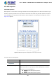
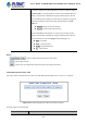
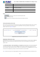


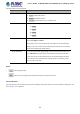
Table Of Contents
- 1. INTRODUCTION
- 2. INSTALLATION
- 3. SWITCH MANAGEMENT
- 4. WEB CONFIGURATION
- 4.1 Main Web Page
- 4.2 System
- 4.2.1 Management
- 4.2.1.1 System Information
- 4.2.1.2 IP Configuration
- 4.2.1.3 IP Status
- 4.2.1.4 Users Configuration
- 4.2.1.5 Privilege Levels
- 4.2.1.6 NTP Configuration
- 4.2.1.6.1 System Time Correction Manually
- 4.2.1.7 Time Configuration
- 4.2.1.8 UPnP
- 4.2.1.9 DHCP Relay
- 4.2.1.10 DHCP Relay Statistics
- 4.2.1.11 CPU Load
- 4.2.1.12 System Log
- 4.2.1.13 Detailed Log
- 4.2.1.14 Remote Syslog
- 4.2.1.15 SMTP Configuration
- 4.2.2 Simple Network Management Protocol
- 4.2.3 RMON
- 4.2.4 DHCP server
- 4.2.1 Management
- 4.3 Switching
- 4.3.1 Port Management
- 4.3.2 Link Aggregation
- 4.3.3 VLAN
- 4.3.3.1 VLAN Overview
- 4.3.3.2 IEEE 802.1Q VLAN
- 4.3.3.3 VLAN Port Configuration
- 4.3.3.4 VLAN Membership Status
- 4.3.3.5 VLAN Port Status
- 4.3.3.6 Port Isolation
- 4.3.3.7 VLAN setting example:
- 4.3.3.7.1 Two Separate 802.1Q VLANs
- 4.3.3.7.2 VLAN Trunking between two 802.1Q aware switches
- 4.3.3.7.3 Port Isolate
- 4.3.3.8 MAC-based VLAN
- 4.3.3.9 IP Subnet-based VLAN
- 4.3.3.10 Protocol-based VLAN
- 4.3.3.11 Protocol-based VLAN Membership
- 4.3.4 Spanning Tree Protocol
- 4.3.5 Multicast
- 4.3.6 MLD Snooping
- 4.3.7 MVR (Multicast VLAN Registration)
- 4.3.8 LLDP
- 4.3.9 MAC Address Table
- 4.3.10 Loop Protection
- 4.3.11 UDLD
- 4.3.12 GVRP
- 4.4 Quality of Service
- 4.5 Security
- 4.6 Power over Ethernet (For WGSW-20160HP/24040HP/24040HP4)
- 4.7 ONVIF
- 4.8 Maintenance
- 5. SWITCH OPERATION
- 6. TROUBLESHOOTING
- APPENDIX A: Networking Connection
- APPENDIX B : GLOSSARY
- EC Declaration of Conformity

User’s Manual of WGSW-24040 and 24040HP Series Managed switch
317
Reserved Power determined by
There are five modes for configuring how the ports/PDs may reserve power and when to shut down ports.
Classification mode
In this mode each port automatically determines how much power to reserve according to the class the connected PD
belongs to, and reserves the power accordingly. Four different port classes exist and one for 4, 7, 15.4 and 30.8 watts.
Class
Usage
Range of maximum power used by the PD
Class Description
0
Default 0.44 to 12.95 watts Classification unimplement
1 Optional 0.44 to 3.84 watts Very low power
2 Optional 3.84 to 6.49 watts Low power
3
Optional 6.49 to 12.95 watts (or to 15.4 watts) Mid power
4
Optional 12.95 to 60 watts (or to 72 watts) High power
Allocation mode
In this mode the user allocates the amount of power that each port may reserve. The allocated/reserved power for each
port/PD is specified in the Maximum Power fields. The ports are shut down when total reserved powered exceeds the
amount of power that the power supply can deliver.
In this mode the port power will not be turned on if the PD requests more available power.
LLDP mode
In this mode the ports of PoE power are managed and determined by LLDP Media Protocol.
4.6.1.3 Power over Ethernet Configuration
This section allows the user to inspect and configure the current PoE configuration settings, as Figure 4-6-1-2 appears.