
WGSW-Series (V3) User Manual
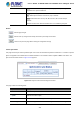

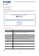

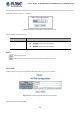

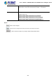
Table Of Contents
- 1. INTRODUCTION
- 2. INSTALLATION
- 3. SWITCH MANAGEMENT
- 4. WEB CONFIGURATION
- 4.1 Main Web Page
- 4.2 System
- 4.2.1 Management
- 4.2.1.1 System Information
- 4.2.1.2 IP Configuration
- 4.2.1.3 IP Status
- 4.2.1.4 Users Configuration
- 4.2.1.5 Privilege Levels
- 4.2.1.6 NTP Configuration
- 4.2.1.6.1 System Time Correction Manually
- 4.2.1.7 Time Configuration
- 4.2.1.8 UPnP
- 4.2.1.9 DHCP Relay
- 4.2.1.10 DHCP Relay Statistics
- 4.2.1.11 CPU Load
- 4.2.1.12 System Log
- 4.2.1.13 Detailed Log
- 4.2.1.14 Remote Syslog
- 4.2.1.15 SMTP Configuration
- 4.2.2 Simple Network Management Protocol
- 4.2.3 RMON
- 4.2.4 DHCP server
- 4.2.1 Management
- 4.3 Switching
- 4.3.1 Port Management
- 4.3.2 Link Aggregation
- 4.3.3 VLAN
- 4.3.3.1 VLAN Overview
- 4.3.3.2 IEEE 802.1Q VLAN
- 4.3.3.3 VLAN Port Configuration
- 4.3.3.4 VLAN Membership Status
- 4.3.3.5 VLAN Port Status
- 4.3.3.6 Port Isolation
- 4.3.3.7 VLAN setting example:
- 4.3.3.7.1 Two Separate 802.1Q VLANs
- 4.3.3.7.2 VLAN Trunking between two 802.1Q aware switches
- 4.3.3.7.3 Port Isolate
- 4.3.3.8 MAC-based VLAN
- 4.3.3.9 IP Subnet-based VLAN
- 4.3.3.10 Protocol-based VLAN
- 4.3.3.11 Protocol-based VLAN Membership
- 4.3.4 Spanning Tree Protocol
- 4.3.5 Multicast
- 4.3.6 MLD Snooping
- 4.3.7 MVR (Multicast VLAN Registration)
- 4.3.8 LLDP
- 4.3.9 MAC Address Table
- 4.3.10 Loop Protection
- 4.3.11 UDLD
- 4.3.12 GVRP
- 4.4 Quality of Service
- 4.5 Security
- 4.6 Power over Ethernet (For WGSW-20160HP/24040HP/24040HP4)
- 4.7 ONVIF
- 4.8 Maintenance
- 5. SWITCH OPERATION
- 6. TROUBLESHOOTING
- APPENDIX A: Networking Connection
- APPENDIX B : GLOSSARY
- EC Declaration of Conformity

User’s Manual of WGSW-24040 and 24040HP Series Managed switch
241
Dport Destination TCP/UDP port:(0-65535) or 'Any', specific or port range
applicable for IP protocol UDP/TCP
• Action Parameters
Class QoS class: (0-7) or 'Default'.
DPL Valid Drop Precedence Level can be (0-3) or 'Default'.
DSCP Valid DSCP value can be (0-63, BE, CS1-CS7, EF or AF11-AF43) or
'Default'.
'Default' means that the default classified value is not modified by this QCE.
Buttons
: Click to apply changes
: Click to undo any changes made locally and revert to previously saved values
: Return to the previous page without saving the configuration change
4.4.5.3 QCL Status
This page shows the QCL status by different QCL users. Each row describes the QCE that is defined. It is a conflict if a specific
QCE is not applied to the hardware due to hardware limitations. The maximum number of QCEs is 256 on each switch. The
QoS Control List Status screen in Figure 4-4-5-3 appears.
Figure 4-4-5-3: QoS Control List Status Page Screenshot
The page includes the following fields:
Object Description
• User
Indicates the QCL user.
• QCE#
Indicates the index of QCE.
• Port
Indicates the list of ports configured with the QCE.
• Frame Type
Indicates the type of frame to look for incoming frames. Possible frame types are: