24-port + 3-slot Stackable Ethernet Switch WGSW-2403 User’s Manual
Trademarks Copyright PLANET Technology Corp. 2003. Contents subject to revision without prior notice. PLANET is a registered trademark of PLANET Technology Corp. to their respective owners. All other trademarks belong Disclaimer PLANET Technology does not warrant that the hardware will work properly in all environments and applications, and makes no warranty and representation, either implied or expressed, with respect to the quality, performance, merchantability, or fitness for a particular purpose.
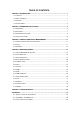
TABLE OF CONTENTS CHAPTER 1 INTRODUCTION .................................................................................................. 1 1.1 CHECKLIST ......................................................................................................................... 1 1.2 ABOUT THE SWITCH ............................................................................................................ 1 1.3 FEATURES .......................................................................................
Chapter 1 INTRODUCTION 1.1 Checklist Check the contents of your package for following parts: l WGSW-2403. l CD-ROM. l Quick Installation Guide l Power cord. l 19” rack-mount brackets. l RS-232 cable. If any of these pieces are missing or damaged, please contact your dealer immediately, if possible, retain the carton including the original packing material, and use them against to repack the product in case there is a need to return it to us for repair. 1.
w Rate control function is provided to restrict each port’s bandwidth provision from 10%, 20% to 100%. w Support 802.1p QoS with two priority queues w Support 802.1Q tagged VLAN, up to 255 VLAN groups can be configured w Console, telnet, web and SNMP manageable w Support IGMP snooping w Port mirroring for dedicated port monitoring 1.
Network Management IEEE 802.
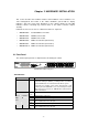
Chapter 2 HARDWARE INSTALLATION This section describes the hardware features and installation of these Switches. For easier management and control of the switch, familiarize yourself with its display indicators, and ports. Front panel illustrations in this chapter display the unit LED indicators. Before connecting any network device to the switch, read this chapter carefully.
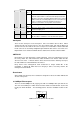
FDX/COL Steady The port is connected at Full-Duplex mode Amber Off Module STACK The port is connected at Half-Duplex mode. A collision occurs when two stations within a collision domain attempt to transmit data at the same time. Intermittent flashing amber of the collision LED is normal; the contending adapters resolve each collision by means of a wait-then-retransmit algorithm.
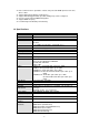
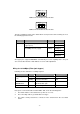
WGSW-D1ST TX RX 100Base-FX 100Base-FX SC multi-mode fiber module WGSW-D1S15 TX RX 100Base-FX 100Base-FX SC multi-mode fiber module The auto-negotiation feature of the switch allows each port of the device running at one of the following operation modes: Port Media Speed 10/100Mbps 100Mbps fiber optic (Alternative to copper port-1) 10/100Mbps RJ-45 (copper) Duplex Mode 100Mbps Full Duplex Half Duplex 10Mbps Full Duplex Half Duplex 100Mbps Full Duplex Half Duplex All copper ports supports MDI/M
4. The connecting device, including any network adapter is well installed and functioning. 5. Confirm the connection distance is implemented within the scope of operative without interference. 2.2 Rear Panel The rear panel of the switch indicates an AC inlet power socket, which accepts input power from 100 to 240VAC, 50-60Hz, one RS-232 console port for setting up the switch via a connection to a terminal or PC using a terminal emulation program, and two slide-in slots for installing additional modules.
Console Port The RS-232 console is an interface for connecting a terminal directly. Through the console port, it provides rich diagnostic information includes network statistics, link status and system setting. The operating mode of the console port is: ♦ DCE ♦ 9600 (Fix baud rate) ♦ n (No parity checking) ♦ 8 (8 Data bits) ♦ 1 (1 stop bit) ♦ None (No flow control) You can use a normal RS-232 cable and connect to the console port on the device.
2. 3. 4. Cabling is away from: w Sources of electrical noise such as radios, transmitters and broadband amplifiers w Power lines and fluorescent lighting fixtures. Keep water or moisture off. Airflow around the unit and through the vents in the side of the case is great for heat radiation (company recommend that you provide a minimum of 25 mm clearance). To prolong the operational life of your units: 1. 2. 3. Never stack unit more than eight sets high if freestanding.
3. 4. Push the module gently into the slot along the slide tracks. Ensuring that it firmly engages with the connector then tighten the screws to secure the module. CAUTION: The slide-in slots are not hot swappable, power off the switch before installing modules. 2.4 Stack Installation There are two RJ-45 ports on the front panel for proprietary management stack. Only straight-through UTP/STP cable can be used. Plug one end of the cable in the “IN” port and the other end to the ”OUT” port of next device.
Chapter 3 CONSOLE AND TELNET MANAGEMENT 3.1 Connect To PC by RS-232 serial Cable NOTE: If you have stacked several switches together, make sure you are working on Master switch (switch with least Switch ID). Other slave switches’ management interface allows only viewing the configuration by “guest” account. To configure the system, connect the provided serial cable to a COM port on a PC or notebook computer and to serial (console) port of the device.
2. Start the Telnet program on a PC and connect to the switch. The management interface is exactly the same with RS-232 console management except the “root” privilege is not supported. 3.3 Main Menu After you enter the switch’s console interface by RS-232 cable or telnet, the following page is shown. Please enter username and password to access WGSW-2403.
Main menu 1. System Information 2. Management Setup 3. Device Control Submenu Function 1. Topology Information Show the Device ID, Hardware version, Boot-up version, POST version, runtime code version, agent status, device name and device location of each switch on the stack. 2. System Information Show detail system information of each switch including their hardware, software version, system up time, system contact, device name, device location and system management capabilities. 3.
6. Mirror Enable or disable the mirror function and choose the sniffer port and monitored port. 7. Statistic Information Show traffic information of each ports. 8. Priority Tag Define the 802.1p tag mapping and the service rule. Please refer to section 4.13 for detail. 9. STA Show the spanning tree algorithm status and configure its parameters. 10. Port Aggregation Enable or disable the port aggregation (port trunking) function on specified ports.
CHAPTER 4 WEB MANAGEMENT 4.1 Start A Web Browser Session TM The Web Interface of WGSW-2403 is coded by Java Applet and running on the Java Virtual Machine (JVM) version 1.3.1 platform. You should configure the management station with an IP address and subnet mask compatible with WGSW-2403 for accessing it. Also, the management station should be well configured and connected to Internet for automatically downloading (upgrading) the suitable JVM through Internet from http://java.sun.com.
4.2 Stack Main Page The stack main page contains two options: Topology This screen displays one or more switches of the management stack. Basic properties can be read by the screen, including Hardware characteristic, Device Name, Up time, Master and Slave relationship. Also, by mouse clicking listed items can enter for further operation.
4.3 Switch Main Page Switch Main Page appears after you click one of the switch(es) on the topology page. There are 8 function button listed on top: Home, Save, Default, Reboot, Ping, Telnet, Contact, and Upgrade. Shortcut to back to stack home page Save the current setting to Non-volatile Memory. The difference between and is that Apply applies settings right away but saves the values in the system memory.
You can specify switch(es) and reboot it. Warm Boot Cold Boot Reboot the switch in a short time. Boot the switch and with fully Power On Self Test (POST). The system is completely checked but spends much time. The Ping is a commonly used tool to detect the remote host or IP address exists or not. Moreover, network status also can be known by the ratio of packets Reply and Loss. By simply clicking the button, the Telnet program implements and displays login screen.
WEB Upload w Select Device ID and “WEB Upload” radio button then click OK. w Specify the file path by clicking Browse button and click Start. TFTP Download 1. Select Device ID and “TFTP Download” radio button then click OK. 2. Enter the TFTP server’s IP address in Server IP field. 3. Enter file name in File Name field. Click Start button to download the code and system update with it automatically Local File Transfer 1. Select Device ID and “Local File Transfer” radio button then click OK. 2.
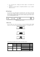
Device The shortcut to go to another member switch in the management stack. 4.4 Device Configuration Panel Display Slide-in Modules MASTER LED SWITCH ID STATUS LED 10/100Mbps Ethernet ports Port Status Port Link Down (Black): Port is not connected or attached device shuts down. Port Link Up (Green): Port links up and working correctly. Port Link Up (Amber): Port links up but in blocking mode. Port Disabled (Red): Port has been disabled.
Network Configuration IP Address: IP address of this device. Subnet Mask: Subnet Mask of your network. Gateway IP: IP address of Gateway. Device Information Name: Naming the system (optional). Contact: Who the System administrator is (optional). Location: Where the management stack locates (optional). NOTE: The Network Configuration and Device Information of Master Device in the management stack will become system parameters automatically. 4.
NOTE: Also by simply clicking the port on the ‘Panel Display’, the port information screen pops up Configuration Port attributes can be setup in this page. Setup Port Attributes 1. Click the “Name” column of the port. Enter a name for identification, like ‘Richard’; and press Enter 2. Leave the “Admin” column ‘Enable’ value to make the port to be in operation or ’Disable’ to pause it 3. Select Duplex mode---10Half/10Full; 100Half/100Full; ‘Auto’ for auto-negotiation and 1000Full auto-detection 4.
NOTE: Also accomplished by simply mouse right-click the port on the ‘Panel Display’ then select ‘Configuration’, the configuration screen pops up. Duplicate Port Attributes Click “Duplicate” button, the dialogue screen appears. 1. Select Source Port (for example Port 1). 2. Select Target Port, click 3. Select the port attributes you want to duplicate. 4. Click 5. Click Apply button to apply settings. 6.
NOTE: Also accomplished by simply mouse right-click the port on the ‘Panel Display’ then select ‘Copy Setting’ to duplicate port properties and select ’Past Setting’ when point at destination port. Statistic The statistics function provides the following 3 pages for various traffic information of each port. There is a Clear button on the bottom of each page for you to clear the statistic data and recount again.
A denominate port can be searched by its given name (Match whole word only). 4.7 Security This is reserved for future use. 4.8 SNMP Simple Network Management Protocol (SNMP) is a communication protocol for managing devices on a network. It is commonly used for network administrators to communicate with multiple devices (hub, switch, router ……) for configuring and monitoring while convenient for troubleshooting but no miscellaneous platform consideration.
1. Select one community you want to modify in the “Current” column 2. The “New” column lists the corresponding values; please modify it 3. Click Modify button to update the entry Trap Manager Trap Manager specifies the Network Management Stations (NMS) that will receive trap messages from the SNMP agent and can up to 5 entries. A Trap Manager entry with Aging Time “0” will never expire; and Aging Time “10” will expire when 10 minutes is up and no more trap messages the corresponding entry can receive.
Trap Filtering Check the “Enable” boxes by mouse clicking to receive a notice when corresponding event occurs. 4.9 VLAN The VLAN is a group of ports that may spread around the network but communicate as though they belong to one subnet. By using VLAN, all ports can be reorganized into separate broadcast domains for security reasons and reduce bandwidth occupation instead of using routers to divide whole network into subnets.
To remove a VLAN group 1. Select a VLAN group you want to remove from the “Current” list. 2. Click Remove>> button to remove it. Attention: 1. If a removed port is no longer belonged to any other group, it is temporarily disabled because no one can communicate with it. 2. If one port’s PVID is equal to this VLAN ID, removing this VLAN group will not allow until you change it. To modify a VLAN group 1. Select a VLAN group you want to modify from the current list 2.
VLAN Port Configuration When the VLAN-enabled switch receives an untagged packet, the packet will be sent to the port’s default VLAN according to the PVID (port VLAN ID) of the receiving port. To change the PVID 1. Double click the “PVID” column of a port. 2. Input a new VLAN ID (1~255). 3. Press “Enter” to submit the value. 4. Click Apply button to apply it. NOTE: 1. All the ports are default as members of VLAN 1 and assigned PVID 1. 2.
Click All Together button then all the ports of the switch will be added to VLAN group 1. - All Independent Click All Independent button then all the ports will be divided into separated subnets (totally 18 subnets). Every port can belong to different Port Group VLANs simultaneously without limitation. 4.10 IGMP Snooping Multicasting is widely used to support multi-media applications such as video conferencing.
However, before making connections between switches, pay attention to: w The ports at both ends of a Port Aggregation connection must be configured as Aggregation Ports. w The ports at both ends of a Port Aggregation connection must have the same port properties, including Speed, Duplex mode. w All the ports of a Port Aggregation must be treated as an integer when added to/deleted from a VLAN. w Spanning Tree Algorithm (STA) treats all the ports of a Port Aggregation as an integer.
Information This screen displays summaries of STA information. For further configuration, please go to next section. Parameter Description STA State Shows if STA is enabled on the switch and participated an STA compliant network. Designated Root The unique Bridge Identifier of the Bridge recorded as the Root in the Configuration BPDUs transmitted by the Designated Bridge for the segment to which the port is attached.
Forward Delay (4~30 sec) This time value, measured in units of a second, controls how fast a port changes its spanning state when moving towards the Forwarding state. The value determines how long the port stays in each of the Listening and Learning states, which precede the Forwarding state. This value is also used, when a topology change has been detected and is underway, to age all dynamic entries in the Forwarding Database.
states, which precede the Forwarding state. This value is also used, when a topology change has been detected and is underway, to age all dynamic entries in the Forwarding Database. STA Port Configuration Parameters Description Port Port number of the port Priority The value of the priority field which is contained in the first (in network byte order) octet of the (2 octet long) Port ID.
FIFO The first in packet, the first out packet (No priority) 1:1 Send 1 high priority packet, then 1 low priority packet 2:1 Send 2 high priority packets, then 1 low priority packet 3:1 Send 3 high priority packets, then 1 low priority packet 4:1 Send 4 high priority packets, then 1 low priority packet 5:1 Send 5 high priority packets, then 1 low priority packet 6:1 Send 6 high priority packets, then 1 low priority packet 7:1 Send 7 high priority packets, then 1 low priority packet 4.
Dynamic Address Counts Number of MAC addresses automatically learned by the current switch. Static Address Counts Number of MAC addresses manually added to the current switch. To add a static address 1. Click the combo box and select a port, then the MAC address table of the port appears. 2. Fill in configuration value (VLAN ID, MAC address), then click “<
- 37 -
CHAPTER 5 TROUBESHOOTING This chapter contains information to help you solve problems. If WGSW-2403 is not functioning properly, make sure the Switch was set up according to instructions in this manual. The port is connected but the port LED is not lit Solution: Check the following items: 1. The switch and the connected device’s power are on or not. 2. The connecting cable is good and with correct type. 3. The cable is firmly seated in its connectors in the switch and in the associated device. 4.
APPENDIX A A.1 Switch‘s RJ-45 Pin Assignments 1000Mbps, 1000Base T Contact MDI MDI-X 1 BI_DA+ BI_DB+ 2 BI_DA- BI_DB- 3 BI_DB+ BI_DA+ 4 BI_DC+ BI_DD+ 5 BI_DC- BI_DD- 6 BI_DB- BI_DA- 7 BI_DD+ BI_DC+ 8 BI_DD- BI_DC- Implicit implementation of the crossover function within a twisted-pair cable, or at a wiring panel, while not expressly forbidden, is beyond the scope of this standard. A.
A.