
WGSW-Series (V3) User Manual
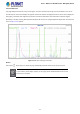

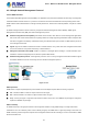
Table Of Contents
- 1. INTRODUCTION
- 2. INSTALLATION
- 3. SWITCH MANAGEMENT
- 4. WEB CONFIGURATION
- 4.1 Main Web Page
- 4.2 System
- 4.2.1 Management
- 4.2.1.1 System Information
- 4.2.1.2 IP Configuration
- 4.2.1.3 IP Status
- 4.2.1.4 ARP Configuration
- 4.2.1.5 Users Configuration
- 4.2.1.6 Privilege Levels
- 4.2.1.7 NTP Configuration
- 4.2.1.7.1 System Time Correction Manually
- 4.2.1.8 Time Configuration
- 4.2.1.9 UPnP
- 4.2.1.10 DHCP Relay
- 4.2.1.11 DHCP Relay Statistics
- 4.2.1.12 CPU Load
- 4.2.1.13 System Log
- 4.2.1.14 Detailed Log
- 4.2.1.15 Remote Syslog
- 4.2.1.16 SMTP Configuration
- 4.2.2 Simple Network Management Protocol
- 4.2.3 RMON
- 4.2.4 DHCP server
- 4.2.5 Remote Management
- 4.2.1 Management
- 4.3 Switching
- 4.3.1 Port Management
- 4.3.2 Link Aggregation
- 4.3.3 VLAN
- 4.3.3.1 VLAN Overview
- 4.3.3.2 IEEE 802.1Q VLAN
- 4.3.3.3 VLAN Port Configuration
- 4.3.3.4 VLAN Membership Status
- 4.3.3.5 VLAN Port Status
- 4.3.3.6 Private VLAN
- 4.3.3.7 Port Isolation
- 4.3.3.8 VLAN setting example:
- 4.3.3.8.1 Two Separate 802.1Q VLANs
- 4.3.3.8.2 VLAN Trunking between two 802.1Q aware switches
- 4.3.3.8.3 Port Isolate
- 4.3.3.9 MAC-based VLAN
- 4.3.3.10 IP Subnet-based VLAN
- 4.3.3.11 Protocol-based VLAN
- 4.3.3.12 Protocol-based VLAN Membership
- 4.3.4 VLAN Translation
- 4.3.5 Spanning Tree Protocol
- 4.3.6 Multicast
- 4.3.6.2 Profile Table
- 4.3.7 MLD Snooping
- 4.3.8 MVR (Multicast VLAN Registration)
- 4.3.9 LLDP
- 4.3.10 MAC Address Table
- 4.3.11 Loop Protection
- 4.3.12 UDLD
- 4.3.13 GVRP
- 4.4 Quality of Service
- 4.5 Security
- 4.6 Power over Ethernet (For WGSW-20160HP/WGSW-24040HP_24040HP4)
- 4.7 ONVIF
- 4.8 Maintenance
- 4.8.1 Web Firmware Upgrade
- 4.8.2 Save Startup Config
- 4.8.3 Configuration Download
- 4.8.4 Configuration Upload
- 4.8.5 Configure Activate
- 4.8.6 Configure Delete
- 4.8.7 Image Select
- 4.8.8 Factory Default
- 4.8.9 System Reboot
- 4.8.10 Ping
- 4.8.11 IPv6 Ping
- 4.8.12 Remote IP Ping
- 4.8.13 Cable Diagnostics
- 4.8.14 Traceroute (IPv4)
- 4.8.15 Traceroute (IPv6)
- 5. SWITCH OPERATION
- APPENDIX A: Networking Connection

User’s Manual of WGSW Series Managed Switch
76
4.2.2 Simple Network Management Protocol
4.2.2.1 SNMP Overview
The Simple Network Management Protocol (SNMP) is an application layer protocol that facilitates the exchange of management
information between network devices. It is part of the Transmission Control Protocol/Internet Protocol (TCP/IP) protocol suite.
SNMP enables network administrators to manage network performance, find and solve network problems, and plan for network
growth.
An SNMP-managed network consists of three key components: Network management stations (NMSs), SNMP agents,
Management information base (MIB) and network-management protocol:
■ Network management stations (NMSs): Sometimes called consoles, these devices execute management applications
that monitor and control network elements. Physically, NMSs are usually engineering workstation-caliber computers with
fast CPUs, megapixel color displays, substantial memory, and abundant disk space. At least one NMS must be present in
each managed environment.
■ Agents: Agents are software modules that reside in network elements. They collect and store management information
such as the number of error packets received by a network element.
■ Management information base (MIB): A MIB is a collection of managed objects residing in a virtual information store.
Collections of related managed objects are defined in specific MIB modules.
■ Network-management protocol: A management protocol is used to convey management information between agents
and NMSs. SNMP is the Internet community's de facto standard management protocol.
Figure 4-2-2-1:
SNMP Operations
SNMP itself is a simple request/response protocol. NMSs can send multiple requests without receiving a response.
■ Get -- Allows the NMS to retrieve an object instance from the agent.
■ Set -- Allows the NMS to set values for object instances within an agent.
■ Trap -- Used by the agent to asynchronously inform the NMS of some event. The SNMPv2 trap message is designed to
replace the SNMPv1 trap message.
SNMP community
An SNMP community is the group that devices and management stations running SNMP belong to. It helps define where
information is sent. The community name is used to identify the group. An SNMP device or agent may belong to more than one
SNMP community. It will not respond to requests from management stations that do not belong to one of its communities. SNMP
default communities are: