
WGSW-Series (V3) User Manual
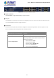

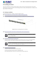
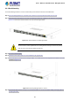
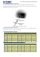
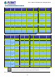
Table Of Contents
- 1. INTRODUCTION
- 2. INSTALLATION
- 3. SWITCH MANAGEMENT
- 4. WEB CONFIGURATION
- 4.1 Main Web Page
- 4.2 System
- 4.2.1 Management
- 4.2.1.1 System Information
- 4.2.1.2 IP Configuration
- 4.2.1.3 IP Status
- 4.2.1.4 ARP Configuration
- 4.2.1.5 Users Configuration
- 4.2.1.6 Privilege Levels
- 4.2.1.7 NTP Configuration
- 4.2.1.7.1 System Time Correction Manually
- 4.2.1.8 Time Configuration
- 4.2.1.9 UPnP
- 4.2.1.10 DHCP Relay
- 4.2.1.11 DHCP Relay Statistics
- 4.2.1.12 CPU Load
- 4.2.1.13 System Log
- 4.2.1.14 Detailed Log
- 4.2.1.15 Remote Syslog
- 4.2.1.16 SMTP Configuration
- 4.2.2 Simple Network Management Protocol
- 4.2.3 RMON
- 4.2.4 DHCP server
- 4.2.5 Remote Management
- 4.2.1 Management
- 4.3 Switching
- 4.3.1 Port Management
- 4.3.2 Link Aggregation
- 4.3.3 VLAN
- 4.3.3.1 VLAN Overview
- 4.3.3.2 IEEE 802.1Q VLAN
- 4.3.3.3 VLAN Port Configuration
- 4.3.3.4 VLAN Membership Status
- 4.3.3.5 VLAN Port Status
- 4.3.3.6 Private VLAN
- 4.3.3.7 Port Isolation
- 4.3.3.8 VLAN setting example:
- 4.3.3.8.1 Two Separate 802.1Q VLANs
- 4.3.3.8.2 VLAN Trunking between two 802.1Q aware switches
- 4.3.3.8.3 Port Isolate
- 4.3.3.9 MAC-based VLAN
- 4.3.3.10 IP Subnet-based VLAN
- 4.3.3.11 Protocol-based VLAN
- 4.3.3.12 Protocol-based VLAN Membership
- 4.3.4 VLAN Translation
- 4.3.5 Spanning Tree Protocol
- 4.3.6 Multicast
- 4.3.6.2 Profile Table
- 4.3.7 MLD Snooping
- 4.3.8 MVR (Multicast VLAN Registration)
- 4.3.9 LLDP
- 4.3.10 MAC Address Table
- 4.3.11 Loop Protection
- 4.3.12 UDLD
- 4.3.13 GVRP
- 4.4 Quality of Service
- 4.5 Security
- 4.6 Power over Ethernet (For WGSW-20160HP/WGSW-24040HP_24040HP4)
- 4.7 ONVIF
- 4.8 Maintenance
- 4.8.1 Web Firmware Upgrade
- 4.8.2 Save Startup Config
- 4.8.3 Configuration Download
- 4.8.4 Configuration Upload
- 4.8.5 Configure Activate
- 4.8.6 Configure Delete
- 4.8.7 Image Select
- 4.8.8 Factory Default
- 4.8.9 System Reboot
- 4.8.10 Ping
- 4.8.11 IPv6 Ping
- 4.8.12 Remote IP Ping
- 4.8.13 Cable Diagnostics
- 4.8.14 Traceroute (IPv4)
- 4.8.15 Traceroute (IPv6)
- 5. SWITCH OPERATION
- APPENDIX A: Networking Connection

User’s Manual of WGSW Series Managed Switch
39
2.2.3 Installing the SFP/SFP+ Transceiver
The sections describe how to insert an SFP/SFP+ transceiver into an SFP/SFP+ slot. The SFP/SFP+ transceivers are
hot-pluggable and hot-swappable. You can plug in and out the transceiver to/from any SFP/SFP+ port without having to power
down the Managed Switch, as the Figure 2-2-4 shows.
Figure 2-2-4: Plug-in the SFP/SFP+ Transceiver
Approved PLANET SFP/SFP+ Transceivers
PLANET Managed Switch supports both single mode and multi-mode SFP/SFP+ transceivers. The following list of approved
PLANET SFP/SFP+ transceivers is correct at the time of publication:
Fast Ethernet Transceiver (100BASE-X SFP)
Model Speed (Mbps) Connector Interface Fiber Mode Distance Wavelength (nm) Operating Temp.
MFB-FX 100 LC Multi Mode 2km 1310nm 0 ~ 60 degrees C
MFB-F20 100 LC Single Mode 20km 1310nm 0 ~ 60 degrees C
MFB-F40 100 LC Single Mode 40km 1310nm 0 ~ 60 degrees C
MFB-F60 100 LC Single Mode 60km 1310nm 0 ~ 60 degrees C
MFB-F120 100 LC Single Mode 120km 1550nm 0 ~ 60 degrees C
MFB-TFX 100 LC Multi Mode 2km 1310nm -40 ~ 75 degrees C
MFB-TF20 100 LC Single Mode 20km 1550nm -40 ~ 75 degrees C
Fast Ethernet Transceiver (100BASE-BX, Single Fiber Bi-directional SFP)
Model Speed (Mbps)
Connector Interface Fiber Mode
Distance
Wavelength (TX/RX) Operating Temp.
MFB-FA20 100 WDM(LC) Single Mode
20km 1310nm/1550nm 0 ~ 60 degrees C
MFB-FB20 100 WDM(LC) Single Mode
20km 1550nm/1310nm 0 ~ 60 degrees C
MFB-TFA20 100 WDM(LC) Single Mode
20km 1310nm/1550nm -40 ~ 75 degrees C
MFB-TFB20 100 WDM(LC) Single Mode
20km 1550nm/1310nm -40 ~ 75 degrees C
MFB-TFA40 100 WDM(LC) Single Mode
40km 1310nm/1550nm -40 ~ 75 degrees C
MFB-TFB40 100 WDM(LC) Single Mode
40km 1550nm/1310nm -40 ~ 75 degrees C