
WGSW-Series (V3) User Manual
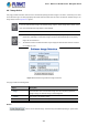
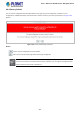
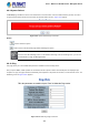
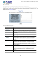

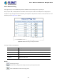
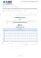
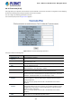
Table Of Contents
- 1. INTRODUCTION
- 2. INSTALLATION
- 3. SWITCH MANAGEMENT
- 4. WEB CONFIGURATION
- 4.1 Main Web Page
- 4.2 System
- 4.2.1 Management
- 4.2.1.1 System Information
- 4.2.1.2 IP Configuration
- 4.2.1.3 IP Status
- 4.2.1.4 ARP Configuration
- 4.2.1.5 Users Configuration
- 4.2.1.6 Privilege Levels
- 4.2.1.7 NTP Configuration
- 4.2.1.7.1 System Time Correction Manually
- 4.2.1.8 Time Configuration
- 4.2.1.9 UPnP
- 4.2.1.10 DHCP Relay
- 4.2.1.11 DHCP Relay Statistics
- 4.2.1.12 CPU Load
- 4.2.1.13 System Log
- 4.2.1.14 Detailed Log
- 4.2.1.15 Remote Syslog
- 4.2.1.16 SMTP Configuration
- 4.2.2 Simple Network Management Protocol
- 4.2.3 RMON
- 4.2.4 DHCP server
- 4.2.5 Remote Management
- 4.2.1 Management
- 4.3 Switching
- 4.3.1 Port Management
- 4.3.2 Link Aggregation
- 4.3.3 VLAN
- 4.3.3.1 VLAN Overview
- 4.3.3.2 IEEE 802.1Q VLAN
- 4.3.3.3 VLAN Port Configuration
- 4.3.3.4 VLAN Membership Status
- 4.3.3.5 VLAN Port Status
- 4.3.3.6 Private VLAN
- 4.3.3.7 Port Isolation
- 4.3.3.8 VLAN setting example:
- 4.3.3.8.1 Two Separate 802.1Q VLANs
- 4.3.3.8.2 VLAN Trunking between two 802.1Q aware switches
- 4.3.3.8.3 Port Isolate
- 4.3.3.9 MAC-based VLAN
- 4.3.3.10 IP Subnet-based VLAN
- 4.3.3.11 Protocol-based VLAN
- 4.3.3.12 Protocol-based VLAN Membership
- 4.3.4 VLAN Translation
- 4.3.5 Spanning Tree Protocol
- 4.3.6 Multicast
- 4.3.6.2 Profile Table
- 4.3.7 MLD Snooping
- 4.3.8 MVR (Multicast VLAN Registration)
- 4.3.9 LLDP
- 4.3.10 MAC Address Table
- 4.3.11 Loop Protection
- 4.3.12 UDLD
- 4.3.13 GVRP
- 4.4 Quality of Service
- 4.5 Security
- 4.6 Power over Ethernet (For WGSW-20160HP/WGSW-24040HP_24040HP4)
- 4.7 ONVIF
- 4.8 Maintenance
- 4.8.1 Web Firmware Upgrade
- 4.8.2 Save Startup Config
- 4.8.3 Configuration Download
- 4.8.4 Configuration Upload
- 4.8.5 Configure Activate
- 4.8.6 Configure Delete
- 4.8.7 Image Select
- 4.8.8 Factory Default
- 4.8.9 System Reboot
- 4.8.10 Ping
- 4.8.11 IPv6 Ping
- 4.8.12 Remote IP Ping
- 4.8.13 Cable Diagnostics
- 4.8.14 Traceroute (IPv4)
- 4.8.15 Traceroute (IPv6)
- 5. SWITCH OPERATION
- APPENDIX A: Networking Connection

User’s Manual of WGSW Series Managed Switch
354
The page includes the following fields:
Object Description
• Hostname or IP
Address
The address of the destination host, either as a symbolic hostname or an IP
Address.
• Payload Size Determines the size of the ICMP data payload in bytes (excluding the size of
Ethernet, IP and ICMP headers). The default value is 56 bytes. The valid range is
2-1452 bytes.
• Payload Data Pattern Determines the pattern used in the ICMP data payload. The default value is 0.
The valid range is 0-255.
• Packet Count Determines the number of PING requests sent. The default value is 5. The valid
range is 1-60.
• TTL Value Determines the Time-To-Live /TTL) field value in the IPv4 header. The default
value is 64. The valid range is 1-255.
• VID for Source
Interface
This field can be used to force the test to use a specific local VLAN interface as
the source interface. Leave this field empty for automatic selection based on
routing configuration.
Note: You may only specify either the VID or the IP Address for the source
interface.
• Source Port Number This field can be used to force the test to use a specific local interface with the
specified port number as the source interface. The specified port must be
configured with a suitable IP address. Leave this field empty for automatic
selection based on routing configuration.
Note: You may only specify either the Source Port Number or the IP Address for
the source interface.
• IP Address for Source
Interface
This field can be used to force the test to use a specific local interface with the
specified IP address as the source interface. The specified IP address must be
configured on a local interface. Leave this field empty for automatic selection
based on routing configuration.
Note: You may only specify either the VID or the IP Address for the source
interface.
• Quiet (only print result) Checking this option will not print the result of each ping request but will only
show the final result.
Be sure the target IP Address is within the same netw
ork subnet of the Managed Switch, or you had
setup the correct gateway IP address.
Buttons
: Click to transmit ICMP packets.