
WGSW-Series (V3) User Manual
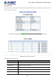
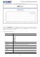
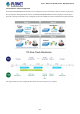


Table Of Contents
- 1. INTRODUCTION
- 2. INSTALLATION
- 3. SWITCH MANAGEMENT
- 4. WEB CONFIGURATION
- 4.1 Main Web Page
- 4.2 System
- 4.2.1 Management
- 4.2.1.1 System Information
- 4.2.1.2 IP Configuration
- 4.2.1.3 IP Status
- 4.2.1.4 ARP Configuration
- 4.2.1.5 Users Configuration
- 4.2.1.6 Privilege Levels
- 4.2.1.7 NTP Configuration
- 4.2.1.7.1 System Time Correction Manually
- 4.2.1.8 Time Configuration
- 4.2.1.9 UPnP
- 4.2.1.10 DHCP Relay
- 4.2.1.11 DHCP Relay Statistics
- 4.2.1.12 CPU Load
- 4.2.1.13 System Log
- 4.2.1.14 Detailed Log
- 4.2.1.15 Remote Syslog
- 4.2.1.16 SMTP Configuration
- 4.2.2 Simple Network Management Protocol
- 4.2.3 RMON
- 4.2.4 DHCP server
- 4.2.5 Remote Management
- 4.2.1 Management
- 4.3 Switching
- 4.3.1 Port Management
- 4.3.2 Link Aggregation
- 4.3.3 VLAN
- 4.3.3.1 VLAN Overview
- 4.3.3.2 IEEE 802.1Q VLAN
- 4.3.3.3 VLAN Port Configuration
- 4.3.3.4 VLAN Membership Status
- 4.3.3.5 VLAN Port Status
- 4.3.3.6 Private VLAN
- 4.3.3.7 Port Isolation
- 4.3.3.8 VLAN setting example:
- 4.3.3.8.1 Two Separate 802.1Q VLANs
- 4.3.3.8.2 VLAN Trunking between two 802.1Q aware switches
- 4.3.3.8.3 Port Isolate
- 4.3.3.9 MAC-based VLAN
- 4.3.3.10 IP Subnet-based VLAN
- 4.3.3.11 Protocol-based VLAN
- 4.3.3.12 Protocol-based VLAN Membership
- 4.3.4 VLAN Translation
- 4.3.5 Spanning Tree Protocol
- 4.3.6 Multicast
- 4.3.6.2 Profile Table
- 4.3.7 MLD Snooping
- 4.3.8 MVR (Multicast VLAN Registration)
- 4.3.9 LLDP
- 4.3.10 MAC Address Table
- 4.3.11 Loop Protection
- 4.3.12 UDLD
- 4.3.13 GVRP
- 4.4 Quality of Service
- 4.5 Security
- 4.6 Power over Ethernet (For WGSW-20160HP/WGSW-24040HP_24040HP4)
- 4.7 ONVIF
- 4.8 Maintenance
- 4.8.1 Web Firmware Upgrade
- 4.8.2 Save Startup Config
- 4.8.3 Configuration Download
- 4.8.4 Configuration Upload
- 4.8.5 Configure Activate
- 4.8.6 Configure Delete
- 4.8.7 Image Select
- 4.8.8 Factory Default
- 4.8.9 System Reboot
- 4.8.10 Ping
- 4.8.11 IPv6 Ping
- 4.8.12 Remote IP Ping
- 4.8.13 Cable Diagnostics
- 4.8.14 Traceroute (IPv4)
- 4.8.15 Traceroute (IPv6)
- 5. SWITCH OPERATION
- APPENDIX A: Networking Connection

User’s Manual of WGSW Series Managed Switch
338
Figure 4-6-1-7: PD Alive Check Configuration Screenshot
The page includes the following fields:
Object Description
• Mode
Allows user to enable or disable per port PD Alive Check function. As default value
all ports are disabled.
• Ping PD IP Address
This coulumn allows user to set PoE device IP address here for system making ping
to the PoE device. Please be noticed that the PD’s IP address must be set to the
same network segment with WGSW-24040HP series Switch.
• Interval Time (2~300s)
This column allows user to set how long system should be issue a ping request to
PD for detecting PD is alive or dead. Interval time range is from 10 seconds to 300
seconds.
• Retry Count (1~5)
This column allows user to set how many times system rerry ping to PD. For
example, if we set count 2, the meaning is that if system retry ping to the PD and the
PD doesn’t response continuously, the PoE port will be reset.
• Action
Allows user to set which action will be apply if the PD witout any response.
WGSW-24040HP series Switch offers 3 actions as following.
1. PD Reboot: It menas system will reset the PoE port that connected the
PD.
2. Reboot & Alarm: It means system will reset the PoE port and issue an
alarm message via Syslog, SMTP.
3. Alarm: It means system will issue an alarm message via Syslog, SMTP.
• PD Reboot Time
(5~180s)
This column allows user to set the PoE device rebooting time, due to there are so
many kind of PoE device on the market and theyhave different rebooting time. The
PD Alive-check is not a defining standard, so the PoE device on the market doesn’t
report reboots done information to WGSW-24040HP series Switch, so user has to
make sure how long the PD will be finished to boot, and then set the time value to