
WGSW-Series (V3) User Manual
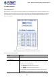
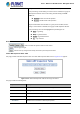

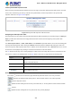
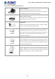
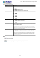
Table Of Contents
- 1. INTRODUCTION
- 2. INSTALLATION
- 3. SWITCH MANAGEMENT
- 4. WEB CONFIGURATION
- 4.1 Main Web Page
- 4.2 System
- 4.2.1 Management
- 4.2.1.1 System Information
- 4.2.1.2 IP Configuration
- 4.2.1.3 IP Status
- 4.2.1.4 ARP Configuration
- 4.2.1.5 Users Configuration
- 4.2.1.6 Privilege Levels
- 4.2.1.7 NTP Configuration
- 4.2.1.7.1 System Time Correction Manually
- 4.2.1.8 Time Configuration
- 4.2.1.9 UPnP
- 4.2.1.10 DHCP Relay
- 4.2.1.11 DHCP Relay Statistics
- 4.2.1.12 CPU Load
- 4.2.1.13 System Log
- 4.2.1.14 Detailed Log
- 4.2.1.15 Remote Syslog
- 4.2.1.16 SMTP Configuration
- 4.2.2 Simple Network Management Protocol
- 4.2.3 RMON
- 4.2.4 DHCP server
- 4.2.5 Remote Management
- 4.2.1 Management
- 4.3 Switching
- 4.3.1 Port Management
- 4.3.2 Link Aggregation
- 4.3.3 VLAN
- 4.3.3.1 VLAN Overview
- 4.3.3.2 IEEE 802.1Q VLAN
- 4.3.3.3 VLAN Port Configuration
- 4.3.3.4 VLAN Membership Status
- 4.3.3.5 VLAN Port Status
- 4.3.3.6 Private VLAN
- 4.3.3.7 Port Isolation
- 4.3.3.8 VLAN setting example:
- 4.3.3.8.1 Two Separate 802.1Q VLANs
- 4.3.3.8.2 VLAN Trunking between two 802.1Q aware switches
- 4.3.3.8.3 Port Isolate
- 4.3.3.9 MAC-based VLAN
- 4.3.3.10 IP Subnet-based VLAN
- 4.3.3.11 Protocol-based VLAN
- 4.3.3.12 Protocol-based VLAN Membership
- 4.3.4 VLAN Translation
- 4.3.5 Spanning Tree Protocol
- 4.3.6 Multicast
- 4.3.6.2 Profile Table
- 4.3.7 MLD Snooping
- 4.3.8 MVR (Multicast VLAN Registration)
- 4.3.9 LLDP
- 4.3.10 MAC Address Table
- 4.3.11 Loop Protection
- 4.3.12 UDLD
- 4.3.13 GVRP
- 4.4 Quality of Service
- 4.5 Security
- 4.6 Power over Ethernet (For WGSW-20160HP/WGSW-24040HP_24040HP4)
- 4.7 ONVIF
- 4.8 Maintenance
- 4.8.1 Web Firmware Upgrade
- 4.8.2 Save Startup Config
- 4.8.3 Configuration Download
- 4.8.4 Configuration Upload
- 4.8.5 Configure Activate
- 4.8.6 Configure Delete
- 4.8.7 Image Select
- 4.8.8 Factory Default
- 4.8.9 System Reboot
- 4.8.10 Ping
- 4.8.11 IPv6 Ping
- 4.8.12 Remote IP Ping
- 4.8.13 Cable Diagnostics
- 4.8.14 Traceroute (IPv4)
- 4.8.15 Traceroute (IPv6)
- 5. SWITCH OPERATION
- APPENDIX A: Networking Connection

User’s Manual of WGSW Series Managed Switch
326
4.6.1.1 Power over Ethernet Powered Device
3~5 watts
Voice over IP phones
Enterprises can install PoE VoIP phones, ATA sand other
Ethernet/non-Ethernet end-devices in the center where UPS is installed for
un-interruptible power system and power control system.
6~12 watts
Wireless LAN Access Points
Access points can be installed at museums, sightseeing sites, airports,
hotels, campuses, factories, warehouses, etc.
10~12 watts
IP Surveillance
IP cameras can be installed at enterprises, museums, campuses, hospitals,
banks, etc. without worrying about electrical outlets.
3~12 watts
PoE Splitter
PoE Splitter split the PoE 56V DC over the Ethernet cable into 5/12V DC
power output. It frees the device deployment from restrictions due to power
outlet locations, which eliminate the costs for additional AC wiring and
reduces the installation time.
3~25 watts
High Power PoE Splitter
High PoE Splitter split the PoE 56V DC over the Ethernet cable into 24/12V
DC power output. It frees the device deployment from restrictions due to
power outlet locations, which eliminate
the costs for additional AC wiring
and reduces the installation time.
30~60 watts
High Power Speed Dome
Its state-of-the-art design fits
in various network environments like traffic
centers, shopping malls, railway stations, warehouses, airports and
production facilities for the most demanding outdoor surveillance
applications. No electricians are needed to install AC sockets.