
WGSW-Series (V3) User Manual
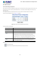
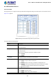
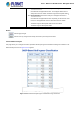
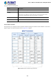
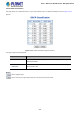
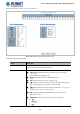
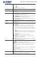
Table Of Contents
- 1. INTRODUCTION
- 2. INSTALLATION
- 3. SWITCH MANAGEMENT
- 4. WEB CONFIGURATION
- 4.1 Main Web Page
- 4.2 System
- 4.2.1 Management
- 4.2.1.1 System Information
- 4.2.1.2 IP Configuration
- 4.2.1.3 IP Status
- 4.2.1.4 ARP Configuration
- 4.2.1.5 Users Configuration
- 4.2.1.6 Privilege Levels
- 4.2.1.7 NTP Configuration
- 4.2.1.7.1 System Time Correction Manually
- 4.2.1.8 Time Configuration
- 4.2.1.9 UPnP
- 4.2.1.10 DHCP Relay
- 4.2.1.11 DHCP Relay Statistics
- 4.2.1.12 CPU Load
- 4.2.1.13 System Log
- 4.2.1.14 Detailed Log
- 4.2.1.15 Remote Syslog
- 4.2.1.16 SMTP Configuration
- 4.2.2 Simple Network Management Protocol
- 4.2.3 RMON
- 4.2.4 DHCP server
- 4.2.5 Remote Management
- 4.2.1 Management
- 4.3 Switching
- 4.3.1 Port Management
- 4.3.2 Link Aggregation
- 4.3.3 VLAN
- 4.3.3.1 VLAN Overview
- 4.3.3.2 IEEE 802.1Q VLAN
- 4.3.3.3 VLAN Port Configuration
- 4.3.3.4 VLAN Membership Status
- 4.3.3.5 VLAN Port Status
- 4.3.3.6 Private VLAN
- 4.3.3.7 Port Isolation
- 4.3.3.8 VLAN setting example:
- 4.3.3.8.1 Two Separate 802.1Q VLANs
- 4.3.3.8.2 VLAN Trunking between two 802.1Q aware switches
- 4.3.3.8.3 Port Isolate
- 4.3.3.9 MAC-based VLAN
- 4.3.3.10 IP Subnet-based VLAN
- 4.3.3.11 Protocol-based VLAN
- 4.3.3.12 Protocol-based VLAN Membership
- 4.3.4 VLAN Translation
- 4.3.5 Spanning Tree Protocol
- 4.3.6 Multicast
- 4.3.6.2 Profile Table
- 4.3.7 MLD Snooping
- 4.3.8 MVR (Multicast VLAN Registration)
- 4.3.9 LLDP
- 4.3.10 MAC Address Table
- 4.3.11 Loop Protection
- 4.3.12 UDLD
- 4.3.13 GVRP
- 4.4 Quality of Service
- 4.5 Security
- 4.6 Power over Ethernet (For WGSW-20160HP/WGSW-24040HP_24040HP4)
- 4.7 ONVIF
- 4.8 Maintenance
- 4.8.1 Web Firmware Upgrade
- 4.8.2 Save Startup Config
- 4.8.3 Configuration Download
- 4.8.4 Configuration Upload
- 4.8.5 Configure Activate
- 4.8.6 Configure Delete
- 4.8.7 Image Select
- 4.8.8 Factory Default
- 4.8.9 System Reboot
- 4.8.10 Ping
- 4.8.11 IPv6 Ping
- 4.8.12 Remote IP Ping
- 4.8.13 Cable Diagnostics
- 4.8.14 Traceroute (IPv4)
- 4.8.15 Traceroute (IPv6)
- 5. SWITCH OPERATION
- APPENDIX A: Networking Connection

User’s Manual of WGSW Series Managed Switch
247
4.4.5 QCL
4.4.5.1 QoS Control List
This page shows the QoS Control List(QCL), which is made up of the QCEs. Each row describes a QCE that is defined. The
maximum number of QCEs is 256 on each switch.
Click on the lowest plus sign to add a new QCE to the list. The QoS Control List screen in Figure 4-4-5-1 appears.
Figure 4-4-5-1: QoS Control List Configuration Page Screenshot
The page includes the following fields:
Object Description
• QCE#
Indicates the index of QCE.
• Port
Indicates the list of ports configured with the QCE.
• DMAC
Specify the type of Destination MAC addresses for incoming frame. Possible
values are:
■ Any: All types of Destination MAC addresses are allowed.
■ Unicast: Only Unicast MAC addresses are allowed.
■ Multicast: Only Multicast MAC addresses are allowed.
■ Broadcast: Only Broadcast MAC addresses are allowed.
The default value is 'Any'.
• SMAC
Displays the OUI field of Source MAC address, i.e. first three octet (byte) of MAC
address.
• Tag Type
Indicates tag type. Possible values are:
■ Any: Match tagged and untagged frames.
■ Untagged: Match untagged frames.
■ Tagged: Match tagged frames.
The default value is 'Any'
• VID
Indicates (VLAN ID), either a specific VID or range of VIDs. VID can be in the
range 1-4095 or 'Any'
• PCP
Priority Code Point: Valid value PCP are specific(0, 1, 2, 3, 4, 5, 6, 7) or
range(0-1, 2-3, 4-5, 6-7, 0-3, 4-7) or 'Any'.
• DEI
Drop Eligible Indicator: Valid value of DEI can be any of values between 0, 1 or
'Any'.
• Frame Type
Indicates the type of frame to look for incoming frames. Possible frame types are:
■ Any: The QCE will match all frame type.