
WGSW-Series (V3) User Manual
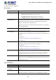
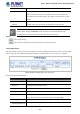
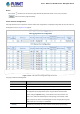
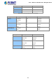
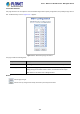
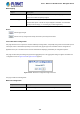
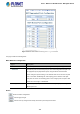
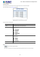
Table Of Contents
- 1. INTRODUCTION
- 2. INSTALLATION
- 3. SWITCH MANAGEMENT
- 4. WEB CONFIGURATION
- 4.1 Main Web Page
- 4.2 System
- 4.2.1 Management
- 4.2.1.1 System Information
- 4.2.1.2 IP Configuration
- 4.2.1.3 IP Status
- 4.2.1.4 ARP Configuration
- 4.2.1.5 Users Configuration
- 4.2.1.6 Privilege Levels
- 4.2.1.7 NTP Configuration
- 4.2.1.7.1 System Time Correction Manually
- 4.2.1.8 Time Configuration
- 4.2.1.9 UPnP
- 4.2.1.10 DHCP Relay
- 4.2.1.11 DHCP Relay Statistics
- 4.2.1.12 CPU Load
- 4.2.1.13 System Log
- 4.2.1.14 Detailed Log
- 4.2.1.15 Remote Syslog
- 4.2.1.16 SMTP Configuration
- 4.2.2 Simple Network Management Protocol
- 4.2.3 RMON
- 4.2.4 DHCP server
- 4.2.5 Remote Management
- 4.2.1 Management
- 4.3 Switching
- 4.3.1 Port Management
- 4.3.2 Link Aggregation
- 4.3.3 VLAN
- 4.3.3.1 VLAN Overview
- 4.3.3.2 IEEE 802.1Q VLAN
- 4.3.3.3 VLAN Port Configuration
- 4.3.3.4 VLAN Membership Status
- 4.3.3.5 VLAN Port Status
- 4.3.3.6 Private VLAN
- 4.3.3.7 Port Isolation
- 4.3.3.8 VLAN setting example:
- 4.3.3.8.1 Two Separate 802.1Q VLANs
- 4.3.3.8.2 VLAN Trunking between two 802.1Q aware switches
- 4.3.3.8.3 Port Isolate
- 4.3.3.9 MAC-based VLAN
- 4.3.3.10 IP Subnet-based VLAN
- 4.3.3.11 Protocol-based VLAN
- 4.3.3.12 Protocol-based VLAN Membership
- 4.3.4 VLAN Translation
- 4.3.5 Spanning Tree Protocol
- 4.3.6 Multicast
- 4.3.6.2 Profile Table
- 4.3.7 MLD Snooping
- 4.3.8 MVR (Multicast VLAN Registration)
- 4.3.9 LLDP
- 4.3.10 MAC Address Table
- 4.3.11 Loop Protection
- 4.3.12 UDLD
- 4.3.13 GVRP
- 4.4 Quality of Service
- 4.5 Security
- 4.6 Power over Ethernet (For WGSW-20160HP/WGSW-24040HP_24040HP4)
- 4.7 ONVIF
- 4.8 Maintenance
- 4.8.1 Web Firmware Upgrade
- 4.8.2 Save Startup Config
- 4.8.3 Configuration Download
- 4.8.4 Configuration Upload
- 4.8.5 Configure Activate
- 4.8.6 Configure Delete
- 4.8.7 Image Select
- 4.8.8 Factory Default
- 4.8.9 System Reboot
- 4.8.10 Ping
- 4.8.11 IPv6 Ping
- 4.8.12 Remote IP Ping
- 4.8.13 Cable Diagnostics
- 4.8.14 Traceroute (IPv4)
- 4.8.15 Traceroute (IPv6)
- 5. SWITCH OPERATION
- APPENDIX A: Networking Connection

User’s Manual of WGSW Series Managed Switch
162
removed from the active topology.
• Port Error Recovery
Control whether a port in the error-disabled state automatically will be enabled
after a certain time. If recovery is not enabled, ports have to be disabled and
re-enabled for normal STP operation. The condition is also cleared by a system
reboot.
• Port Error Recovery
Timeout
The time that has to pass before a port in the error-disabled state can be
enabled. Valid values are between 30 and 86400 seconds (24 hours).
The Managed Switch implements the Rapid Spanning Protocol as the default spanning tree
protocol. When selecting “Compatibles” mode, the system uses the RSTP (802.1w) to be
compatible and to co-work with another STP (802.1D)’s BPDU control packet.
Buttons
: Click to apply changes
: Click to undo any changes made locally and revert to previously saved values.
4.3.5.3 Bridge Status
This page provides a status overview for all STP bridge instances. The displayed table contains a row for each STP bridge
instance, where the column displays the following information: The Bridge Status screen in Figure 4-3-5-5 appears.
Figure 4-3-5-5: STP Bridge Status Page Screenshot
The page includes the following fields:
Object Description
• MSTI
The Bridge Instance. This is also a link to the STP Detailed Bridge Status.
• Bridge ID
The Bridge ID of this Bridge instance.
• Root ID
The Bridge ID of the currently elected root bridge.
• Root Port
The switch port currently assigned the root port role.
• Root Cost
Root Path Cost. For the Root Bridge this is zero. For all other Bridges, it is the
sum of the Port Path Costs on the least cost path to the Root Bridge.
• Topology Flag
The current state of the Topology Change Flag for this Bridge instance.
• Topology Change Last
The time since last Topology Change occurred.