
WGSW-Series (V3) User Manual
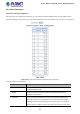
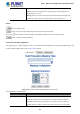
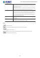
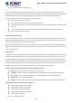
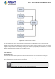
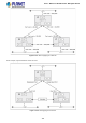
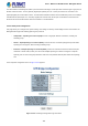
Table Of Contents
- 1. INTRODUCTION
- 2. INSTALLATION
- 3. SWITCH MANAGEMENT
- 4. WEB CONFIGURATION
- 4.1 Main Web Page
- 4.2 System
- 4.2.1 Management
- 4.2.1.1 System Information
- 4.2.1.2 IP Configuration
- 4.2.1.3 IP Status
- 4.2.1.4 ARP Configuration
- 4.2.1.5 Users Configuration
- 4.2.1.6 Privilege Levels
- 4.2.1.7 NTP Configuration
- 4.2.1.7.1 System Time Correction Manually
- 4.2.1.8 Time Configuration
- 4.2.1.9 UPnP
- 4.2.1.10 DHCP Relay
- 4.2.1.11 DHCP Relay Statistics
- 4.2.1.12 CPU Load
- 4.2.1.13 System Log
- 4.2.1.14 Detailed Log
- 4.2.1.15 Remote Syslog
- 4.2.1.16 SMTP Configuration
- 4.2.2 Simple Network Management Protocol
- 4.2.3 RMON
- 4.2.4 DHCP server
- 4.2.5 Remote Management
- 4.2.1 Management
- 4.3 Switching
- 4.3.1 Port Management
- 4.3.2 Link Aggregation
- 4.3.3 VLAN
- 4.3.3.1 VLAN Overview
- 4.3.3.2 IEEE 802.1Q VLAN
- 4.3.3.3 VLAN Port Configuration
- 4.3.3.4 VLAN Membership Status
- 4.3.3.5 VLAN Port Status
- 4.3.3.6 Private VLAN
- 4.3.3.7 Port Isolation
- 4.3.3.8 VLAN setting example:
- 4.3.3.8.1 Two Separate 802.1Q VLANs
- 4.3.3.8.2 VLAN Trunking between two 802.1Q aware switches
- 4.3.3.8.3 Port Isolate
- 4.3.3.9 MAC-based VLAN
- 4.3.3.10 IP Subnet-based VLAN
- 4.3.3.11 Protocol-based VLAN
- 4.3.3.12 Protocol-based VLAN Membership
- 4.3.4 VLAN Translation
- 4.3.5 Spanning Tree Protocol
- 4.3.6 Multicast
- 4.3.6.2 Profile Table
- 4.3.7 MLD Snooping
- 4.3.8 MVR (Multicast VLAN Registration)
- 4.3.9 LLDP
- 4.3.10 MAC Address Table
- 4.3.11 Loop Protection
- 4.3.12 UDLD
- 4.3.13 GVRP
- 4.4 Quality of Service
- 4.5 Security
- 4.6 Power over Ethernet (For WGSW-20160HP/WGSW-24040HP_24040HP4)
- 4.7 ONVIF
- 4.8 Maintenance
- 4.8.1 Web Firmware Upgrade
- 4.8.2 Save Startup Config
- 4.8.3 Configuration Download
- 4.8.4 Configuration Upload
- 4.8.5 Configure Activate
- 4.8.6 Configure Delete
- 4.8.7 Image Select
- 4.8.8 Factory Default
- 4.8.9 System Reboot
- 4.8.10 Ping
- 4.8.11 IPv6 Ping
- 4.8.12 Remote IP Ping
- 4.8.13 Cable Diagnostics
- 4.8.14 Traceroute (IPv4)
- 4.8.15 Traceroute (IPv6)
- 5. SWITCH OPERATION
- APPENDIX A: Networking Connection

User’s Manual of WGSW Series Managed Switch
160
The switch with the lowest Bridge ID (switch C) was elected the root bridge, and the ports were selected to give a high port cost
between switches B and C. The two (optional) Gigabit ports (default port cost = 20,000) on switch A are connected to one
(optional) Gigabit port on both switch B and C. The redundant link between switch B and C is deliberately chosen as a 100 Mbps
Fast Ethernet link (default port cost = 200,000). Gigabit ports could be used, but the port cost should be increased from the
default to ensure that the link between switch B and switch C is the blocked link.
4.3.5.2 STP System Configuration
This page allows you to configure STP system settings. The settings are used by all STP Bridge instances in the Switch. The
Managed Switch support the following Spanning Tree protocols:
‧ Compatiable -- Spanning Tree Protocol (STP):Provides a single path between end stations, avoiding and
eliminating loops.
‧ Normal -- Rapid Spanning Tree Protocol (RSTP) : Detects and uses of network topologies that provide faster
spanning tree convergence, without creating forwarding loops.
‧ Extension – Multiple Spanning Tree Protocol (MSTP) : Defines an extension to RSTP to further develop the
usefulness of virtual LANs (VLANs). This "Per-VLAN" Multiple Spanning Tree Protocol configures a separate
Spanning Tree for each VLAN group and blocks all but one of the possible alternate paths within each Spanning
Tree.
The STP System Configuration screen in Figure 4-3-5-4 appears.
Figure 4-3-5-4: STP Bridge Configuration Page Screenshot