
WGSW-Series (V3) User Manual
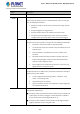
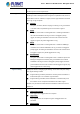
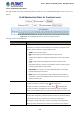

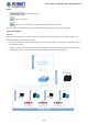
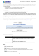
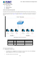
Table Of Contents
- 1. INTRODUCTION
- 2. INSTALLATION
- 3. SWITCH MANAGEMENT
- 4. WEB CONFIGURATION
- 4.1 Main Web Page
- 4.2 System
- 4.2.1 Management
- 4.2.1.1 System Information
- 4.2.1.2 IP Configuration
- 4.2.1.3 IP Status
- 4.2.1.4 ARP Configuration
- 4.2.1.5 Users Configuration
- 4.2.1.6 Privilege Levels
- 4.2.1.7 NTP Configuration
- 4.2.1.7.1 System Time Correction Manually
- 4.2.1.8 Time Configuration
- 4.2.1.9 UPnP
- 4.2.1.10 DHCP Relay
- 4.2.1.11 DHCP Relay Statistics
- 4.2.1.12 CPU Load
- 4.2.1.13 System Log
- 4.2.1.14 Detailed Log
- 4.2.1.15 Remote Syslog
- 4.2.1.16 SMTP Configuration
- 4.2.2 Simple Network Management Protocol
- 4.2.3 RMON
- 4.2.4 DHCP server
- 4.2.5 Remote Management
- 4.2.1 Management
- 4.3 Switching
- 4.3.1 Port Management
- 4.3.2 Link Aggregation
- 4.3.3 VLAN
- 4.3.3.1 VLAN Overview
- 4.3.3.2 IEEE 802.1Q VLAN
- 4.3.3.3 VLAN Port Configuration
- 4.3.3.4 VLAN Membership Status
- 4.3.3.5 VLAN Port Status
- 4.3.3.6 Private VLAN
- 4.3.3.7 Port Isolation
- 4.3.3.8 VLAN setting example:
- 4.3.3.8.1 Two Separate 802.1Q VLANs
- 4.3.3.8.2 VLAN Trunking between two 802.1Q aware switches
- 4.3.3.8.3 Port Isolate
- 4.3.3.9 MAC-based VLAN
- 4.3.3.10 IP Subnet-based VLAN
- 4.3.3.11 Protocol-based VLAN
- 4.3.3.12 Protocol-based VLAN Membership
- 4.3.4 VLAN Translation
- 4.3.5 Spanning Tree Protocol
- 4.3.6 Multicast
- 4.3.6.2 Profile Table
- 4.3.7 MLD Snooping
- 4.3.8 MVR (Multicast VLAN Registration)
- 4.3.9 LLDP
- 4.3.10 MAC Address Table
- 4.3.11 Loop Protection
- 4.3.12 UDLD
- 4.3.13 GVRP
- 4.4 Quality of Service
- 4.5 Security
- 4.6 Power over Ethernet (For WGSW-20160HP/WGSW-24040HP_24040HP4)
- 4.7 ONVIF
- 4.8 Maintenance
- 4.8.1 Web Firmware Upgrade
- 4.8.2 Save Startup Config
- 4.8.3 Configuration Download
- 4.8.4 Configuration Upload
- 4.8.5 Configure Activate
- 4.8.6 Configure Delete
- 4.8.7 Image Select
- 4.8.8 Factory Default
- 4.8.9 System Reboot
- 4.8.10 Ping
- 4.8.11 IPv6 Ping
- 4.8.12 Remote IP Ping
- 4.8.13 Cable Diagnostics
- 4.8.14 Traceroute (IPv4)
- 4.8.15 Traceroute (IPv6)
- 5. SWITCH OPERATION
- APPENDIX A: Networking Connection

User’s Manual of WGSW Series Managed Switch
139
For private VLANs to be applied, the switch must first be configured for standard VLAN operation When this is in place, one or
more of the configured VLANs can be configured as private VLANs. Ports in a private VLAN fall into one of these two groups:
Promiscuous ports
— Ports from which traffic can be forwarded to all ports in the private VLAN
— Ports which can receive traffic from all ports in the private VLAN
Isolated ports
— Ports from which traffic can only be forwarded to promiscuous ports in the private VLAN
— Ports which can receive traffic from only promiscuous ports in the private VLAN
The configuration of promiscuous and isolated ports applies to all private VLANs. When traffic comes in on a promiscuous port
in a private VLAN, the VLAN mask from the VLAN table is applied. When traffic comes in on an isolated port, the private VLAN
mask is applied in addition to the VLAN mask from the VLAN table. This reduces the ports to which forwarding can be done to
just the promiscuous ports within the private VLAN.
This page is used for enabling or disabling port isolation on ports in a Private VLAN. A port member of a VLAN can be isolated
to other isolated ports on the same VLAN and Private VLAN. The Port Isolation screen in Figure 4-6-7 appears.
Figure 4-6-7: Port Isolation Configuration Page Screenshot
The page includes the following fields:
Object Description
• Port Members
A check box is provided for each port of a private VLAN. When checked, port
isolation is enabled on that port. When unchecked, port isolation is disabled on
that port.
By default, port isolation is disabled on all ports.
Buttons
: Click to apply changes
: Click to undo any changes made locally and revert to previously saved values.
Auto-refresh : Check this box to refresh the page automatically. Automatic refresh occurs every 3 seconds.
: Click to refresh the page immediately.