
User Manual
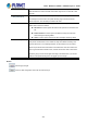


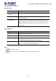

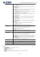


Table Of Contents
- 1. INTRODUCTION
- 2. INSTALLATION
- 3. SWITCH MANAGEMENT
- 4. WEB CONFIGURATION
- 4.1 Main Web Page
- 4.2 System
- 4.2.1 System Information
- 4.2.2 IP Configuration
- 4.2.3 IP Status
- 4.2.4 Users Configuration
- 4.2.5 Privilege Levels
- 4.2.6 NTP Configuration
- 4.2.7 Time Configuration
- 4.2.8 UPnP
- 4.2.9 DHCP Relay
- 4.2.10 DHCP Relay Statistics
- 4.2.11 CPU Load
- 4.2.12 System Log
- 4.2.13 Detailed Log
- 4.2.14 Remote Syslog
- 4.2.15 SMTP Configuration
- 4.2.16 Web Firmware Upgrade
- 4.2.17 TFTP Firmware Upgrade
- 4.2.18 Save Startup Config
- 4.2.19 Configuration Download
- 4.2.20 Configuration Upload
- 4.2.21 Configuration Activate
- 4.2.22 Configuration Delete
- 4.2.23 Image Select
- 4.2.24 Factory Default
- 4.2.25 System Reboot
- 4.3 Simple Network Management Protocol
- 4.4 Port Management
- 4.5 Link Aggregation
- 4.6 VLAN
- 4.6.1 VLAN Overview
- 4.6.2 IEEE 802.1Q VLAN
- 4.6.3 VLAN Port Configuration
- 4.6.4 VLAN Membership Status
- 4.6.5 VLAN Port Status
- 4.6.6 Port Isolation
- 4.6.7 VLAN setting example:
- 4.6.8 MAC-based VLAN
- 4.6.9 MAC-based VLAN Status
- 4.6.10 IP Subnet-based VLAN
- 4.6.11 Protocol-based VLAN
- 4.6.12 Protocol-based VLAN Membership
- 4.7 Spanning Tree Protocol
- 4.8 Multicast
- 4.8.1 IGMP Snooping
- 4.8.2 Profile Table
- 4.8.3 Address Entry
- 4.8.4 IGMP Snooping Configuration
- 4.8.5 IGMP Snooping VLAN Configuration
- 4.8.6 IGMP Snooping Port Group Filtering
- 4.8.7 IGMP Snooping Status
- 4.8.8 IGMP Group Information
- 4.8.9 IGMPv3 Information
- 4.8.10 MLD Snooping Configuration
- 4.8.11 MLD Snooping VLAN Configuration
- 4.8.12 MLD Snooping Port Group Filtering
- 4.8.13 MLD Snooping Status
- 4.8.14 MLD Group Information
- 4.8.15 MLDv2 Information
- 4.8.16 MVR (Multicaset VLAN Registration)
- 4.8.17 MVR Status
- 4.8.18 MVR Groups Information
- 4.8.19 MVR SFM Information
- 4.9 Quality of Service
- 4.9.1 Understanding QoS
- 4.9.2 Port Policing
- 4.9.3 Port Classification
- 4.9.4 Port Scheduler
- 4.9.5 Port Shaping
- 4.9.6 Port Tag Remarking
- 4.9.7 Port DSCP
- 4.9.8 DSCP-based QoS
- 4.9.9 DSCP Translation
- 4.9.10 DSCP Classification
- 4.9.11 QoS Control List
- 4.9.12 QCL Status
- 4.9.13 Storm Control Configuration
- 4.9.14 QoS Statistics
- 4.9.15 Voice VLAN Configuration
- 4.9.16 Voice VLAN OUI Table
- 4.10 Access Control Lists
- 4.11 Authentication
- 4.11.1 Understanding IEEE 802.1X Port-based Authentication
- 4.11.2 Authentication Configuration
- 4.11.3 Network Access Server Configuration
- 4.11.4 Network Access Overview
- 4.11.5 Network Access Statistics
- 4.11.6 RADIUS
- 4.11.7 TACACS+
- 4.11.8 RADIUS Overview
- 4.11.9 RADIUS Details
- 4.11.10 Windows Platform RADIUS Server Configuration
- 4.11.11 802.1X Client Configuration
- 4.12 Security
- 4.12.1 Port Limit Control
- 4.12.2 Access Management
- 4.12.3 Access Management Statistics
- 4.12.4 HTTPs
- 4.12.5 SSH
- 4.12.6 Port Security Status
- 4.12.7 Port Security Detail
- 4.12.8 DHCP Snooping
- 4.12.9 Snooping Table
- 4.12.10 IP Source Guard Configuration
- 4.12.11 IP Source Guard Static Table
- 4.12.12 ARP Inspection
- 4.12.13 ARP Inspection Static Table
- 4.13 Address Table
- 4.14 LLDP
- 4.15 Network Diagnostics
- 4.16 Power over Ethernet (PoE series only)
- 4.17 Loop Protection
- 4.18 RMON
- 5. SWITCH OPERATION
- 6. Power over Ethernet Overview
- 7. TROUBLESHOOTING
- APPENDIX A: Networking Connection
- APPENDIX B : GLOSSARY
- EC Declaration of Conformity

User’s Manual of WGSD / WGSW Layer 2+ Series
Interval Time (10~300s)
This column allows user to set how long system should issue a ping request to PD to
detecte whether PD is alive or dead. Interval time range is from 10 seconds to 300
seconds.
Retry Count (1~5)
This column allows user to set how many times system retries ping to PD.
For example, if we set count 2, the system will retry ping to the PD but the PD
doesn’t response. Then the PoE port needs to be reset.
Action
Allows user to set which action it will apply if the PD does not respond. The PoE
Switch offers 3 actions as follows:
PD Reboot: It means system will reset the PoE port that is connected to the
PD.
Reboot & Alarm: It means system will reset the PoE port and issue an
alarm message via Syslog, SMTP.
Alarm: It means system will issue an alarm message via Syslog, SMTP.
Reboot Time (30~180s)
This column allows user to set the PoE device rebooting time, due to there are so
many kinds of PoE devices on the market and they have different rebooting time.
The PD alive-check is not a defining standard, so the PoE device on the market
doesn’t report reboots done information to the PoE Switch. User has to make sure
how long the PD will be finished to boot, and then set the time value to this column.
System is going to check the PD again according to the reboot time. If you cannot
make sure the precise booting time, we suggest you set it longer.
Buttons
: Click to apply changes
: Click it to reset configuration which has not been saved yet.
331