
User Manual


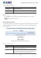
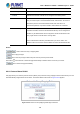


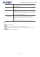
Table Of Contents
- 1. INTRODUCTION
- 2. INSTALLATION
- 3. SWITCH MANAGEMENT
- 4. WEB CONFIGURATION
- 4.1 Main Web Page
- 4.2 System
- 4.2.1 System Information
- 4.2.2 IP Configuration
- 4.2.3 IP Status
- 4.2.4 Users Configuration
- 4.2.5 Privilege Levels
- 4.2.6 NTP Configuration
- 4.2.7 Time Configuration
- 4.2.8 UPnP
- 4.2.9 DHCP Relay
- 4.2.10 DHCP Relay Statistics
- 4.2.11 CPU Load
- 4.2.12 System Log
- 4.2.13 Detailed Log
- 4.2.14 Remote Syslog
- 4.2.15 SMTP Configuration
- 4.2.16 Web Firmware Upgrade
- 4.2.17 TFTP Firmware Upgrade
- 4.2.18 Save Startup Config
- 4.2.19 Configuration Download
- 4.2.20 Configuration Upload
- 4.2.21 Configuration Activate
- 4.2.22 Configuration Delete
- 4.2.23 Image Select
- 4.2.24 Factory Default
- 4.2.25 System Reboot
- 4.3 Simple Network Management Protocol
- 4.4 Port Management
- 4.5 Link Aggregation
- 4.6 VLAN
- 4.6.1 VLAN Overview
- 4.6.2 IEEE 802.1Q VLAN
- 4.6.3 VLAN Port Configuration
- 4.6.4 VLAN Membership Status
- 4.6.5 VLAN Port Status
- 4.6.6 Port Isolation
- 4.6.7 VLAN setting example:
- 4.6.8 MAC-based VLAN
- 4.6.9 MAC-based VLAN Status
- 4.6.10 IP Subnet-based VLAN
- 4.6.11 Protocol-based VLAN
- 4.6.12 Protocol-based VLAN Membership
- 4.7 Spanning Tree Protocol
- 4.8 Multicast
- 4.8.1 IGMP Snooping
- 4.8.2 Profile Table
- 4.8.3 Address Entry
- 4.8.4 IGMP Snooping Configuration
- 4.8.5 IGMP Snooping VLAN Configuration
- 4.8.6 IGMP Snooping Port Group Filtering
- 4.8.7 IGMP Snooping Status
- 4.8.8 IGMP Group Information
- 4.8.9 IGMPv3 Information
- 4.8.10 MLD Snooping Configuration
- 4.8.11 MLD Snooping VLAN Configuration
- 4.8.12 MLD Snooping Port Group Filtering
- 4.8.13 MLD Snooping Status
- 4.8.14 MLD Group Information
- 4.8.15 MLDv2 Information
- 4.8.16 MVR (Multicaset VLAN Registration)
- 4.8.17 MVR Status
- 4.8.18 MVR Groups Information
- 4.8.19 MVR SFM Information
- 4.9 Quality of Service
- 4.9.1 Understanding QoS
- 4.9.2 Port Policing
- 4.9.3 Port Classification
- 4.9.4 Port Scheduler
- 4.9.5 Port Shaping
- 4.9.6 Port Tag Remarking
- 4.9.7 Port DSCP
- 4.9.8 DSCP-based QoS
- 4.9.9 DSCP Translation
- 4.9.10 DSCP Classification
- 4.9.11 QoS Control List
- 4.9.12 QCL Status
- 4.9.13 Storm Control Configuration
- 4.9.14 QoS Statistics
- 4.9.15 Voice VLAN Configuration
- 4.9.16 Voice VLAN OUI Table
- 4.10 Access Control Lists
- 4.11 Authentication
- 4.11.1 Understanding IEEE 802.1X Port-based Authentication
- 4.11.2 Authentication Configuration
- 4.11.3 Network Access Server Configuration
- 4.11.4 Network Access Overview
- 4.11.5 Network Access Statistics
- 4.11.6 RADIUS
- 4.11.7 TACACS+
- 4.11.8 RADIUS Overview
- 4.11.9 RADIUS Details
- 4.11.10 Windows Platform RADIUS Server Configuration
- 4.11.11 802.1X Client Configuration
- 4.12 Security
- 4.12.1 Port Limit Control
- 4.12.2 Access Management
- 4.12.3 Access Management Statistics
- 4.12.4 HTTPs
- 4.12.5 SSH
- 4.12.6 Port Security Status
- 4.12.7 Port Security Detail
- 4.12.8 DHCP Snooping
- 4.12.9 Snooping Table
- 4.12.10 IP Source Guard Configuration
- 4.12.11 IP Source Guard Static Table
- 4.12.12 ARP Inspection
- 4.12.13 ARP Inspection Static Table
- 4.13 Address Table
- 4.14 LLDP
- 4.15 Network Diagnostics
- 4.16 Power over Ethernet (PoE series only)
- 4.17 Loop Protection
- 4.18 RMON
- 5. SWITCH OPERATION
- 6. Power over Ethernet Overview
- 7. TROUBLESHOOTING
- APPENDIX A: Networking Connection
- APPENDIX B : GLOSSARY
- EC Declaration of Conformity

User’s Manual of WGSD / WGSW Layer 2+ Series
IP Address
Indicates the IP address.
Mask Length
Indicates the network mask length.
VLAN ID
Indicates the VLAN ID. VLAN ID can be changed for the existing entries.
Port Members
A row of check boxes for each port is displayed for each IP subnet-based VLAN
entry. To include a port in a IP subnet-based VLAN, check the box. To remove or
exclude the port from the IP subnet-based VLAN, make sure the box is
unchecked. By default, no ports are members, and all boxes are unchecked.
Add New Entry
Click “Add New Entry” to add a new IP subnet-based VLAN entry. An empty row
is added to the table, and the IP subnet-based VLAN entry can be configured as
needed. Any IP address/mask can be configured for the IP subnet-based VLAN
entry. Legal values for a VLAN ID are 1 through 4095.
The IP subnet-based VLAN entry is enabled when you click on "Save". The
“Delete” button can be used to undo the addition of new IP subnet-based VLANs.
Buttons
: Click to add a new entry in mapping table.
: Click to apply changes
: Click to undo any changes made locally and revert to previously saved values.
Auto-refresh
: Check this box to refresh the page automatically. Automatic refresh occurs every 3 seconds.
: Click to refresh the page immediately.
4.6.1 Protocol-based VLAN
This page allows you to add new protocols to Group Name (unique for each Group) mapping entries as well as allow you to see
and delete already mapped entries for the switch. The Protocol-based VLAN screen in Figure 4-6-22 appears.
Figure 4-6-22: Protocol to Group Mapping Table Page Screenshot
136