
User Manual
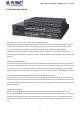
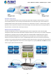


Table Of Contents
- 1. INTRODUCTION
- 2. INSTALLATION
- 3. SWITCH MANAGEMENT
- 4. WEB CONFIGURATION
- 4.1 Main Web Page
- 4.2 System
- 4.2.1 System Information
- 4.2.2 IP Configuration
- 4.2.3 IP Status
- 4.2.4 Users Configuration
- 4.2.5 Privilege Levels
- 4.2.6 NTP Configuration
- 4.2.7 Time Configuration
- 4.2.8 UPnP
- 4.2.9 DHCP Relay
- 4.2.10 DHCP Relay Statistics
- 4.2.11 CPU Load
- 4.2.12 System Log
- 4.2.13 Detailed Log
- 4.2.14 Remote Syslog
- 4.2.15 SMTP Configuration
- 4.2.16 Web Firmware Upgrade
- 4.2.17 TFTP Firmware Upgrade
- 4.2.18 Save Startup Config
- 4.2.19 Configuration Download
- 4.2.20 Configuration Upload
- 4.2.21 Configuration Activate
- 4.2.22 Configuration Delete
- 4.2.23 Image Select
- 4.2.24 Factory Default
- 4.2.25 System Reboot
- 4.3 Simple Network Management Protocol
- 4.4 Port Management
- 4.5 Link Aggregation
- 4.6 VLAN
- 4.6.1 VLAN Overview
- 4.6.2 IEEE 802.1Q VLAN
- 4.6.3 VLAN Port Configuration
- 4.6.4 VLAN Membership Status
- 4.6.5 VLAN Port Status
- 4.6.6 Port Isolation
- 4.6.7 VLAN setting example:
- 4.6.8 MAC-based VLAN
- 4.6.9 MAC-based VLAN Status
- 4.6.10 IP Subnet-based VLAN
- 4.6.11 Protocol-based VLAN
- 4.6.12 Protocol-based VLAN Membership
- 4.7 Spanning Tree Protocol
- 4.8 Multicast
- 4.8.1 IGMP Snooping
- 4.8.2 Profile Table
- 4.8.3 Address Entry
- 4.8.4 IGMP Snooping Configuration
- 4.8.5 IGMP Snooping VLAN Configuration
- 4.8.6 IGMP Snooping Port Group Filtering
- 4.8.7 IGMP Snooping Status
- 4.8.8 IGMP Group Information
- 4.8.9 IGMPv3 Information
- 4.8.10 MLD Snooping Configuration
- 4.8.11 MLD Snooping VLAN Configuration
- 4.8.12 MLD Snooping Port Group Filtering
- 4.8.13 MLD Snooping Status
- 4.8.14 MLD Group Information
- 4.8.15 MLDv2 Information
- 4.8.16 MVR (Multicaset VLAN Registration)
- 4.8.17 MVR Status
- 4.8.18 MVR Groups Information
- 4.8.19 MVR SFM Information
- 4.9 Quality of Service
- 4.9.1 Understanding QoS
- 4.9.2 Port Policing
- 4.9.3 Port Classification
- 4.9.4 Port Scheduler
- 4.9.5 Port Shaping
- 4.9.6 Port Tag Remarking
- 4.9.7 Port DSCP
- 4.9.8 DSCP-based QoS
- 4.9.9 DSCP Translation
- 4.9.10 DSCP Classification
- 4.9.11 QoS Control List
- 4.9.12 QCL Status
- 4.9.13 Storm Control Configuration
- 4.9.14 QoS Statistics
- 4.9.15 Voice VLAN Configuration
- 4.9.16 Voice VLAN OUI Table
- 4.10 Access Control Lists
- 4.11 Authentication
- 4.11.1 Understanding IEEE 802.1X Port-based Authentication
- 4.11.2 Authentication Configuration
- 4.11.3 Network Access Server Configuration
- 4.11.4 Network Access Overview
- 4.11.5 Network Access Statistics
- 4.11.6 RADIUS
- 4.11.7 TACACS+
- 4.11.8 RADIUS Overview
- 4.11.9 RADIUS Details
- 4.11.10 Windows Platform RADIUS Server Configuration
- 4.11.11 802.1X Client Configuration
- 4.12 Security
- 4.12.1 Port Limit Control
- 4.12.2 Access Management
- 4.12.3 Access Management Statistics
- 4.12.4 HTTPs
- 4.12.5 SSH
- 4.12.6 Port Security Status
- 4.12.7 Port Security Detail
- 4.12.8 DHCP Snooping
- 4.12.9 Snooping Table
- 4.12.10 IP Source Guard Configuration
- 4.12.11 IP Source Guard Static Table
- 4.12.12 ARP Inspection
- 4.12.13 ARP Inspection Static Table
- 4.13 Address Table
- 4.14 LLDP
- 4.15 Network Diagnostics
- 4.16 Power over Ethernet (PoE series only)
- 4.17 Loop Protection
- 4.18 RMON
- 5. SWITCH OPERATION
- 6. Power over Ethernet Overview
- 7. TROUBLESHOOTING
- APPENDIX A: Networking Connection
- APPENDIX B : GLOSSARY
- EC Declaration of Conformity

User’s Manual of WGSD / WGSW Layer 2+ Series
Powerful Security
The Layer 2+ Gigabit Managed Switch series offers comprehensive Layer 2 to Layer 4 Access Control List (ACL) for
enforcing security to the edge. It can be used to restrict network access by denying packets based on source and destination
IP address, TCP/UDP ports or defined typical network applications. Its protection mechanism also comprises 802.1x
port-based and MAC-based user and device authentication. With the private VLAN function, communication between edge
ports can be prevented to ensure user privacy.
Enhanced Security and Traffic Control
The Layer 2+ Gigabit Managed Switch series also provides DHCP Snooping, IP Source Guard and Dynamic ARP
Inspection functions to prevent IP snooping from attack and discard ARP packets with invalid MAC address. The network
administrators can now construct highly-secured corporate networks with considerably less time and effort than before.
Flexibility and Extension Solution
The mini-GBIC slots built in the Layer 2+ Gigabit Managed Switch series support dual-speed as it features 100Base-FX and
1000BASE-SX/LX SFP (Small Form-factor Pluggable) fiber-optic modules, meaning the administrator now can flexibly
choose the suitable SFP transceiver according to not only the transmission distance but also the transmission speed required.
The distance can be extended from 550 meters (multi-mode fiber) and up to above 10/50/70/120 kilometers (single-mode
fiber or WDM fiber). They are well suited for applications within the enterprise data centers and distributions.
Intelligent SFP Diagnostic Mechanism
The Layer 2+ Gigabit Managed Switch series supports SFP-DDM (Digital Diagnostic Monitor) function that can easily
monitor real-time parameters of the SFP for network administrator, such as optical output power, optical input power,
temperature, laser bias current, and transceiver supply voltage.
Centralized Power Management for Gigabit Ethernet PoE Networking (WGSD-10020HP / WGSW-20160HP
/ WGSW-24040HP series)
To fulfill the needs of higher power required PoE network applications with Gigabit speed transmission, the WGSD-10020
PoE series / WGSW-20160HP / WGSW-24040 PoE series features high-performance Gigabit IEEE 802.3af PoE (Up to
15.4W) and IEEE 802.3at High-Power PoE (Up to 30.8W) on all ports. It supports advanced networking feature which
optimizes the installation and power management of network devices such as wireless access points (AP), Voice over IP
(VoIP) phones, and security video cameras. The PoE capabilities also help to reduce deployment costs for network devices
like the wireless AP as a result of freeing from restrictions of power outlet locations. Power and data switching are integrated
into one unit and delivered over a single cable. It thus eliminates cost for additional AC wiring and reduces installation time.
13