
User Manual
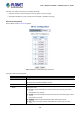


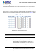
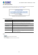
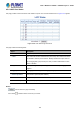
Table Of Contents
- 1. INTRODUCTION
- 2. INSTALLATION
- 3. SWITCH MANAGEMENT
- 4. WEB CONFIGURATION
- 4.1 Main Web Page
- 4.2 System
- 4.2.1 System Information
- 4.2.2 IP Configuration
- 4.2.3 IP Status
- 4.2.4 Users Configuration
- 4.2.5 Privilege Levels
- 4.2.6 NTP Configuration
- 4.2.7 Time Configuration
- 4.2.8 UPnP
- 4.2.9 DHCP Relay
- 4.2.10 DHCP Relay Statistics
- 4.2.11 CPU Load
- 4.2.12 System Log
- 4.2.13 Detailed Log
- 4.2.14 Remote Syslog
- 4.2.15 SMTP Configuration
- 4.2.16 Web Firmware Upgrade
- 4.2.17 TFTP Firmware Upgrade
- 4.2.18 Save Startup Config
- 4.2.19 Configuration Download
- 4.2.20 Configuration Upload
- 4.2.21 Configuration Activate
- 4.2.22 Configuration Delete
- 4.2.23 Image Select
- 4.2.24 Factory Default
- 4.2.25 System Reboot
- 4.3 Simple Network Management Protocol
- 4.4 Port Management
- 4.5 Link Aggregation
- 4.6 VLAN
- 4.6.1 VLAN Overview
- 4.6.2 IEEE 802.1Q VLAN
- 4.6.3 VLAN Port Configuration
- 4.6.4 VLAN Membership Status
- 4.6.5 VLAN Port Status
- 4.6.6 Port Isolation
- 4.6.7 VLAN setting example:
- 4.6.8 MAC-based VLAN
- 4.6.9 MAC-based VLAN Status
- 4.6.10 IP Subnet-based VLAN
- 4.6.11 Protocol-based VLAN
- 4.6.12 Protocol-based VLAN Membership
- 4.7 Spanning Tree Protocol
- 4.8 Multicast
- 4.8.1 IGMP Snooping
- 4.8.2 Profile Table
- 4.8.3 Address Entry
- 4.8.4 IGMP Snooping Configuration
- 4.8.5 IGMP Snooping VLAN Configuration
- 4.8.6 IGMP Snooping Port Group Filtering
- 4.8.7 IGMP Snooping Status
- 4.8.8 IGMP Group Information
- 4.8.9 IGMPv3 Information
- 4.8.10 MLD Snooping Configuration
- 4.8.11 MLD Snooping VLAN Configuration
- 4.8.12 MLD Snooping Port Group Filtering
- 4.8.13 MLD Snooping Status
- 4.8.14 MLD Group Information
- 4.8.15 MLDv2 Information
- 4.8.16 MVR (Multicaset VLAN Registration)
- 4.8.17 MVR Status
- 4.8.18 MVR Groups Information
- 4.8.19 MVR SFM Information
- 4.9 Quality of Service
- 4.9.1 Understanding QoS
- 4.9.2 Port Policing
- 4.9.3 Port Classification
- 4.9.4 Port Scheduler
- 4.9.5 Port Shaping
- 4.9.6 Port Tag Remarking
- 4.9.7 Port DSCP
- 4.9.8 DSCP-based QoS
- 4.9.9 DSCP Translation
- 4.9.10 DSCP Classification
- 4.9.11 QoS Control List
- 4.9.12 QCL Status
- 4.9.13 Storm Control Configuration
- 4.9.14 QoS Statistics
- 4.9.15 Voice VLAN Configuration
- 4.9.16 Voice VLAN OUI Table
- 4.10 Access Control Lists
- 4.11 Authentication
- 4.11.1 Understanding IEEE 802.1X Port-based Authentication
- 4.11.2 Authentication Configuration
- 4.11.3 Network Access Server Configuration
- 4.11.4 Network Access Overview
- 4.11.5 Network Access Statistics
- 4.11.6 RADIUS
- 4.11.7 TACACS+
- 4.11.8 RADIUS Overview
- 4.11.9 RADIUS Details
- 4.11.10 Windows Platform RADIUS Server Configuration
- 4.11.11 802.1X Client Configuration
- 4.12 Security
- 4.12.1 Port Limit Control
- 4.12.2 Access Management
- 4.12.3 Access Management Statistics
- 4.12.4 HTTPs
- 4.12.5 SSH
- 4.12.6 Port Security Status
- 4.12.7 Port Security Detail
- 4.12.8 DHCP Snooping
- 4.12.9 Snooping Table
- 4.12.10 IP Source Guard Configuration
- 4.12.11 IP Source Guard Static Table
- 4.12.12 ARP Inspection
- 4.12.13 ARP Inspection Static Table
- 4.13 Address Table
- 4.14 LLDP
- 4.15 Network Diagnostics
- 4.16 Power over Ethernet (PoE series only)
- 4.17 Loop Protection
- 4.18 RMON
- 5. SWITCH OPERATION
- 6. Power over Ethernet Overview
- 7. TROUBLESHOOTING
- APPENDIX A: Networking Connection
- APPENDIX B : GLOSSARY
- EC Declaration of Conformity

User’s Manual of WGSD / WGSW Layer 2+ Series
Disconnect all link aggregation port cables or disable the link aggregation ports before removing a port link aggregation to
avoid creating a data loop.
It allows a maximum of 10 ports to be aggregated at the same time. The Managed Switch support Gigabit Ethernet ports (up to 5
groups). If the group is defined as a LACP static link aggregationing group, then any extra ports selected are placed in a standby
mode for redundancy if one of the other ports fails. If the group is defined as a local static link aggregationing group, then the
number of ports must be the same as the group member ports.
The aggregation code ensures that frames belonging to the same frame flow (for example, a TCP connection) are always
forwarded on the same link aggregation member port. Reording of frames within a flow is therefore not possible. The
aggregation code is based on the following information:
Source MAC
Destination MAC
Source and destination IPv4 address.
Source and destination TCP/UDP ports for IPv4 packets
Normally, all 5 contributions to the aggregation code should be enabled to obtain the best traffic distribution among the link
aggregation member ports. Each link aggregation may consist of up to 10 member ports. Any quantity of link aggregation s may
be configured for the device (only limited by the quantity of ports on the device.) To configure a proper traffic distribution, the
ports within a link aggregation must use the same link speed.
4.5.1 Static Aggregation
This page is used to configure the Aggregation hash mode and the aggregation group. The aggregation hash mode settings are
global, whereas the aggregation group relate to the currently unit, as reflected by the Page header.
Hash Code Contributors
The Static Aggeration screen in Figure 4-5-2 appears.
Figure 4-5-2 : Aggregation Mode Configuration Page Screenshot
The page includes the following fields:
Object Description
Source MAC Address
The Source MAC address can be used to calculate the destination port for the
frame. Check to enable the use of the Source MAC address, or uncheck to
105