
Gigabit Ethernet Switch User's Manual
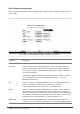

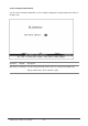
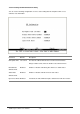
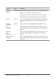
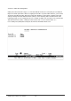
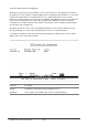
Table Of Contents
- Chapter 1. Introduction
- Chapter 2. Installing the Switch
- Chapter 3. Switch Management
- Chapter 4. Console Interface
- 4.1 Login Screen
- 4.2 Main Menu
- 4.3 System Information Menu
- 4.4 Management Setup Menu
- 4.5 Device Control Menu
- 4.5.1 Setting the System Operation Mode
- 4.5.2 Layer 2 Menu
- 4.5.3 Using the Bridge Menu
- 4.5.4 Configuring Virtual LANs
- 4.5.5 Configuring IGMP Snooping
- 4.5.6 Configuring IP Settings
- 4.5.7 Security Menu
- 4.5.8 Jumbo Packet Configuration
- 4.6 Monitoring the Switch
- 4.6.1 Displaying Port Statistics
- 4.6.2 Layer 2 Address Tables
- 4.6.3 Displaying Bridge Information
- 4.6.4 Displaying VLAN Information
- 4.6.5 IP Multicast Registration Table
- 4.6.6 IP Address Table
- 4.7 Resetting the System
- 4.8 Logging Off the System
- Chapter 5. Web Interface
- 5.1 Web-Based Configuration and Monitoring
- 5.2 Navigating the Web Browser Interface
- 5.3 Panel Display
- 5.4 Main Menu
- 5.5 System Information Menu
- 5.6 Management Setup Menu
- 5.7 Device Control Menu
- 5.7.1 Layer 2 Menu
- 5.7.2 Using the Bridge Menu
- 5.7.3 Configuring Virtual LANs
- 5.7.4 Configuring IGMP Snooping
- 5.7.5 Configuring IP Settings
- 5.7.6 Configuring Security Filters
- 5.7.7 Jumbo Packet Configuration
- 5.8 Monitoring the Switch
- 5.9 Resetting the System
- Chapter 6.Advanced Topics
- Appendix A Troubleshooting
- Appendix B Pin Assignments
- GLOSSARY
WGS3 Layer 3 Switch User’s Manual
- 82 -
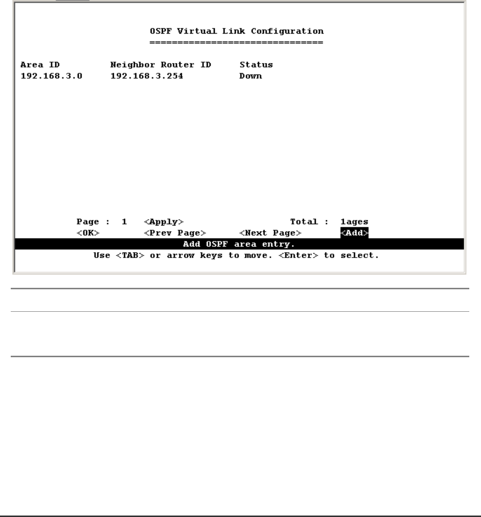
4.5.6.2.3.3 OSPF Virtual Link Configuration
All OSPF areas must connect to the backbone. If an area does not have a direct physical connection to
the backbone, you can configure a virtual link that provides a logical path to the backbone. To connect an
isolated area to the backbone, the logical path can cross a single nonbackbone area to reach the
backbone. To define the path, you must specify one endpoint on the ABR that connects the isolated area
to the common nonbackbone area, and the other endpoint on the ABR that connects this common
nonbackbone area and the backbone itself. (However, note that you cannot configure a virtual link that
runs through a stub or NSSA area.)
Virtual links can also be used to create a redundant link between any area and the backbone to help
prevent partitioning, or to connect two existing backbone areas into a common backbone.
To configure a virtual link, specify the transit area through which the endpoint routers connect, and the
address of the router on this side of the link.
Parameter Description
Area ID An identifier for the transit area the virtual link crosses
Neighbor IP The IP address of the OSPF router on this end of the virtual link.