
Gigabit Ethernet Switch User's Manual

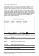
Table Of Contents
- Chapter 1. Introduction
- Chapter 2. Installing the Switch
- Chapter 3. Switch Management
- Chapter 4. Console Interface
- 4.1 Login Screen
- 4.2 Main Menu
- 4.3 System Information Menu
- 4.4 Management Setup Menu
- 4.5 Device Control Menu
- 4.5.1 Setting the System Operation Mode
- 4.5.2 Layer 2 Menu
- 4.5.3 Using the Bridge Menu
- 4.5.4 Configuring Virtual LANs
- 4.5.5 Configuring IGMP Snooping
- 4.5.6 Configuring IP Settings
- 4.5.7 Security Menu
- 4.5.8 Jumbo Packet Configuration
- 4.6 Monitoring the Switch
- 4.6.1 Displaying Port Statistics
- 4.6.2 Layer 2 Address Tables
- 4.6.3 Displaying Bridge Information
- 4.6.4 Displaying VLAN Information
- 4.6.5 IP Multicast Registration Table
- 4.6.6 IP Address Table
- 4.7 Resetting the System
- 4.8 Logging Off the System
- Chapter 5. Web Interface
- 5.1 Web-Based Configuration and Monitoring
- 5.2 Navigating the Web Browser Interface
- 5.3 Panel Display
- 5.4 Main Menu
- 5.5 System Information Menu
- 5.6 Management Setup Menu
- 5.7 Device Control Menu
- 5.7.1 Layer 2 Menu
- 5.7.2 Using the Bridge Menu
- 5.7.3 Configuring Virtual LANs
- 5.7.4 Configuring IGMP Snooping
- 5.7.5 Configuring IP Settings
- 5.7.6 Configuring Security Filters
- 5.7.7 Jumbo Packet Configuration
- 5.8 Monitoring the Switch
- 5.9 Resetting the System
- Chapter 6.Advanced Topics
- Appendix A Troubleshooting
- Appendix B Pin Assignments
- GLOSSARY

WGS3 Layer 3 Switch User’s Manual
- 78 -
Parameter Default Description
Router ID
Selection
STATIC INTF Defines how the Router ID is determined: There are three options:
STATIC: User can manual configure the Router ID.
STATIC INTF: The VLAN 1 IP address will be used as Router ID
ACTIVE INTF: The first active interface will be used as Router ID
Router ID VLAN 1 IP A 32-bit number assigned to each router running the OSPF protocol.
This number uniquely identifies the router within an Autonomous
System.
RFC 1583
Compatibility
Disabled Enable or disable the compatibility to RFC 1583 OSPF version 2
Area ID
Configuration
Defines an area within which all OSPF routers actively exchange
routing information to ensure that they all have an identical link state
database.
OSPF Area
Range
Configuration
Defines a range of subnetwork addresses. An area range is used to
summarize route information exchanged between Area Border
Routers.
OSPF Virtual Link
Configuration
Defines a virtual link that can be used to connect an OSPF area not
physically adjacent to the OSPF backbone, or to create a backup link
to any area.