
Gigabit Ethernet Switch User's Manual
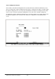
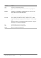
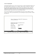
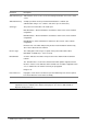
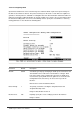
Table Of Contents
- Chapter 1. Introduction
- Chapter 2. Installing the Switch
- Chapter 3. Switch Management
- Chapter 4. Console Interface
- 4.1 Login Screen
- 4.2 Main Menu
- 4.3 System Information Menu
- 4.4 Management Setup Menu
- 4.5 Device Control Menu
- 4.5.1 Setting the System Operation Mode
- 4.5.2 Layer 2 Menu
- 4.5.3 Using the Bridge Menu
- 4.5.4 Configuring Virtual LANs
- 4.5.5 Configuring IGMP Snooping
- 4.5.6 Configuring IP Settings
- 4.5.7 Security Menu
- 4.5.8 Jumbo Packet Configuration
- 4.6 Monitoring the Switch
- 4.6.1 Displaying Port Statistics
- 4.6.2 Layer 2 Address Tables
- 4.6.3 Displaying Bridge Information
- 4.6.4 Displaying VLAN Information
- 4.6.5 IP Multicast Registration Table
- 4.6.6 IP Address Table
- 4.7 Resetting the System
- 4.8 Logging Off the System
- Chapter 5. Web Interface
- 5.1 Web-Based Configuration and Monitoring
- 5.2 Navigating the Web Browser Interface
- 5.3 Panel Display
- 5.4 Main Menu
- 5.5 System Information Menu
- 5.6 Management Setup Menu
- 5.7 Device Control Menu
- 5.7.1 Layer 2 Menu
- 5.7.2 Using the Bridge Menu
- 5.7.3 Configuring Virtual LANs
- 5.7.4 Configuring IGMP Snooping
- 5.7.5 Configuring IP Settings
- 5.7.6 Configuring Security Filters
- 5.7.7 Jumbo Packet Configuration
- 5.8 Monitoring the Switch
- 5.9 Resetting the System
- Chapter 6.Advanced Topics
- Appendix A Troubleshooting
- Appendix B Pin Assignments
- GLOSSARY
WGS3 Layer 3 Switch User’s Manual
- 69 -
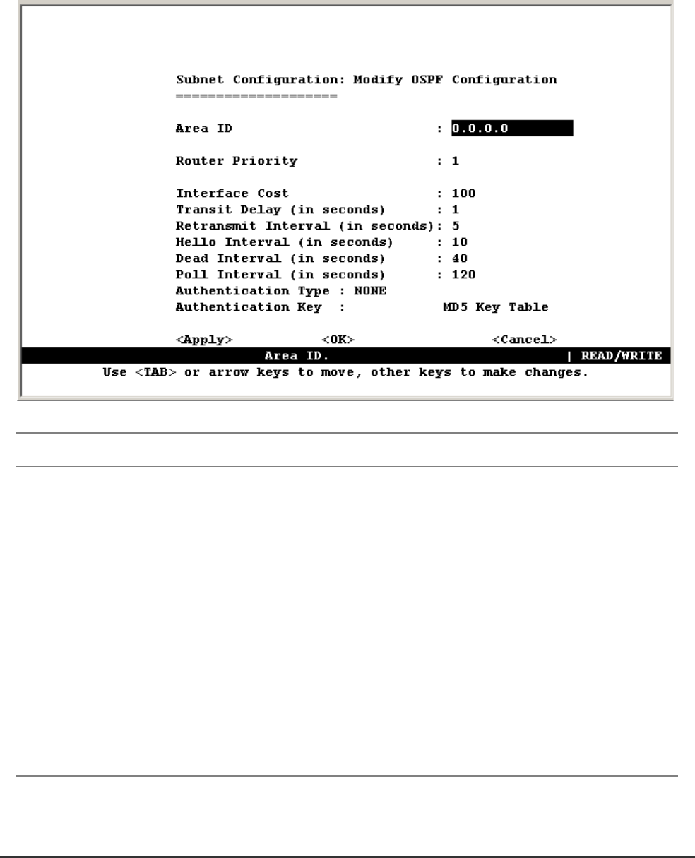
4.5.6.1.5 Configuring OSPF
Open Shortest Path First is more suited for large area networks which experience frequent changes in
the links. It also allows for subnets. This protocol actively tests the status of each link to its neighbors to
generate a shortest path tree, and builds a routing table based on this information. OSPF then utilizes IP
multicast to propagate routing information. A separate routing area scheme is also used to further reduce
the amount of routing traffic. You can use the following menu to specify the area identifier, or other key
routing parameters as described in the following table.
Parameter Default Description
Area ID
*1
0.0.0.0 A 32-bit integer uniquely identifying an OSPF protocol broadcast area
This identifier can be in the form of an IP address or integer. Each
port on the switch can be configured to represent one OSPF area.
You must first specify OSPF areas for global access in the Area ID
Configuration menu, before they can be used for a specific IP
interface.
ID 0.0.0.0 is used for the OSPF backbone.
Router Priority
1 The priority used when selecting the designated router and
designated backup router.
Range: 0-255; Disable election: 0
Interface Cost 100 Explicitly specify the cost of sending a packet on the interface.
Range: 1-65535