
Gigabit Ethernet Switch User's Manual
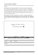
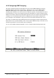

Table Of Contents
- Chapter 1. Introduction
- Chapter 2. Installing the Switch
- Chapter 3. Switch Management
- Chapter 4. Console Interface
- 4.1 Login Screen
- 4.2 Main Menu
- 4.3 System Information Menu
- 4.4 Management Setup Menu
- 4.5 Device Control Menu
- 4.5.1 Setting the System Operation Mode
- 4.5.2 Layer 2 Menu
- 4.5.3 Using the Bridge Menu
- 4.5.4 Configuring Virtual LANs
- 4.5.5 Configuring IGMP Snooping
- 4.5.6 Configuring IP Settings
- 4.5.7 Security Menu
- 4.5.8 Jumbo Packet Configuration
- 4.6 Monitoring the Switch
- 4.6.1 Displaying Port Statistics
- 4.6.2 Layer 2 Address Tables
- 4.6.3 Displaying Bridge Information
- 4.6.4 Displaying VLAN Information
- 4.6.5 IP Multicast Registration Table
- 4.6.6 IP Address Table
- 4.7 Resetting the System
- 4.8 Logging Off the System
- Chapter 5. Web Interface
- 5.1 Web-Based Configuration and Monitoring
- 5.2 Navigating the Web Browser Interface
- 5.3 Panel Display
- 5.4 Main Menu
- 5.5 System Information Menu
- 5.6 Management Setup Menu
- 5.7 Device Control Menu
- 5.7.1 Layer 2 Menu
- 5.7.2 Using the Bridge Menu
- 5.7.3 Configuring Virtual LANs
- 5.7.4 Configuring IGMP Snooping
- 5.7.5 Configuring IP Settings
- 5.7.6 Configuring Security Filters
- 5.7.7 Jumbo Packet Configuration
- 5.8 Monitoring the Switch
- 5.9 Resetting the System
- Chapter 6.Advanced Topics
- Appendix A Troubleshooting
- Appendix B Pin Assignments
- GLOSSARY

WGS3 Layer 3 Switch User’s Manual
- 54 -
member of the associated VLAN, these frames are stripped of all VLAN tags prior to transmission.)
3: If you want to create a small port-based VLAN for just one or two switches, you can assign ports to the
same untagged VLAN (and use a separate connection where a VLAN crosses the switches). However,
to participate in a VLAN group that extends beyond this switch, we recommend using the VLAN ID for
that group (using VLAN tagging for Layer 2 mode, or a common PVID for multilayer mode).
When operating the switch in Layer 2 mode, ports assigned to a large VLAN group that crosses several
switches must use VLAN tagging. But when operating in multilayer mode, this switch does not currently
support tagging, so you should set the PVID to the same value at both ends of the link (if the device you
are attaching to is VLAN-aware), and configure an IP interface for this VLAN if you need to connect it to
other group.
This parameter is for WGS3-2620 only. WGS3-404’s default setting is Rx All and use VLAN Table
Configuration for Tx.
Parameter Default Description
GVRP Enabled Enables or disables GVRP for this port. When disabled, any GVRP
packets received on this port will be discarded and no GVRP registrations
will be propagated from other ports.
Note that GVRP must be enabled globally for the switch before this
setting can take effect. (See “4.5.3.1 Configuring Global Bridge Settings”)
GMRP
*4
Enabled Enables or disables GMRP for this port. When enabled, this port will allow
end stations to register with multicast groups using GMRP. Note that
GMRP must be enabled for the switch before this setting can take effect.
IGMP and IGMP Snooping also provide multicast filtering. (See “6.4.2
IGMP Protocol”)
Ingress
Filtering
*5
Disabled If enabled, incoming frames for VLANs which do not include this ingress
port in their member set will be discarded at the ingress port.
4: Only displayed on WGS3-2620.
5: This control does not affect VLAN independent BPDU frames, such as GVRP or STP. However, they
do affect VLAN dependent BPDU frames, such as GMRP.