
Gigabit Ethernet Switch User's Manual
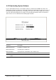
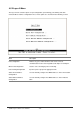
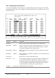
Table Of Contents
- Chapter 1. Introduction
- Chapter 2. Installing the Switch
- Chapter 3. Switch Management
- Chapter 4. Console Interface
- 4.1 Login Screen
- 4.2 Main Menu
- 4.3 System Information Menu
- 4.4 Management Setup Menu
- 4.5 Device Control Menu
- 4.5.1 Setting the System Operation Mode
- 4.5.2 Layer 2 Menu
- 4.5.3 Using the Bridge Menu
- 4.5.4 Configuring Virtual LANs
- 4.5.5 Configuring IGMP Snooping
- 4.5.6 Configuring IP Settings
- 4.5.7 Security Menu
- 4.5.8 Jumbo Packet Configuration
- 4.6 Monitoring the Switch
- 4.6.1 Displaying Port Statistics
- 4.6.2 Layer 2 Address Tables
- 4.6.3 Displaying Bridge Information
- 4.6.4 Displaying VLAN Information
- 4.6.5 IP Multicast Registration Table
- 4.6.6 IP Address Table
- 4.7 Resetting the System
- 4.8 Logging Off the System
- Chapter 5. Web Interface
- 5.1 Web-Based Configuration and Monitoring
- 5.2 Navigating the Web Browser Interface
- 5.3 Panel Display
- 5.4 Main Menu
- 5.5 System Information Menu
- 5.6 Management Setup Menu
- 5.7 Device Control Menu
- 5.7.1 Layer 2 Menu
- 5.7.2 Using the Bridge Menu
- 5.7.3 Configuring Virtual LANs
- 5.7.4 Configuring IGMP Snooping
- 5.7.5 Configuring IP Settings
- 5.7.6 Configuring Security Filters
- 5.7.7 Jumbo Packet Configuration
- 5.8 Monitoring the Switch
- 5.9 Resetting the System
- Chapter 6.Advanced Topics
- Appendix A Troubleshooting
- Appendix B Pin Assignments
- GLOSSARY
WGS3 Layer 3 Switch User’s Manual
- 38 -
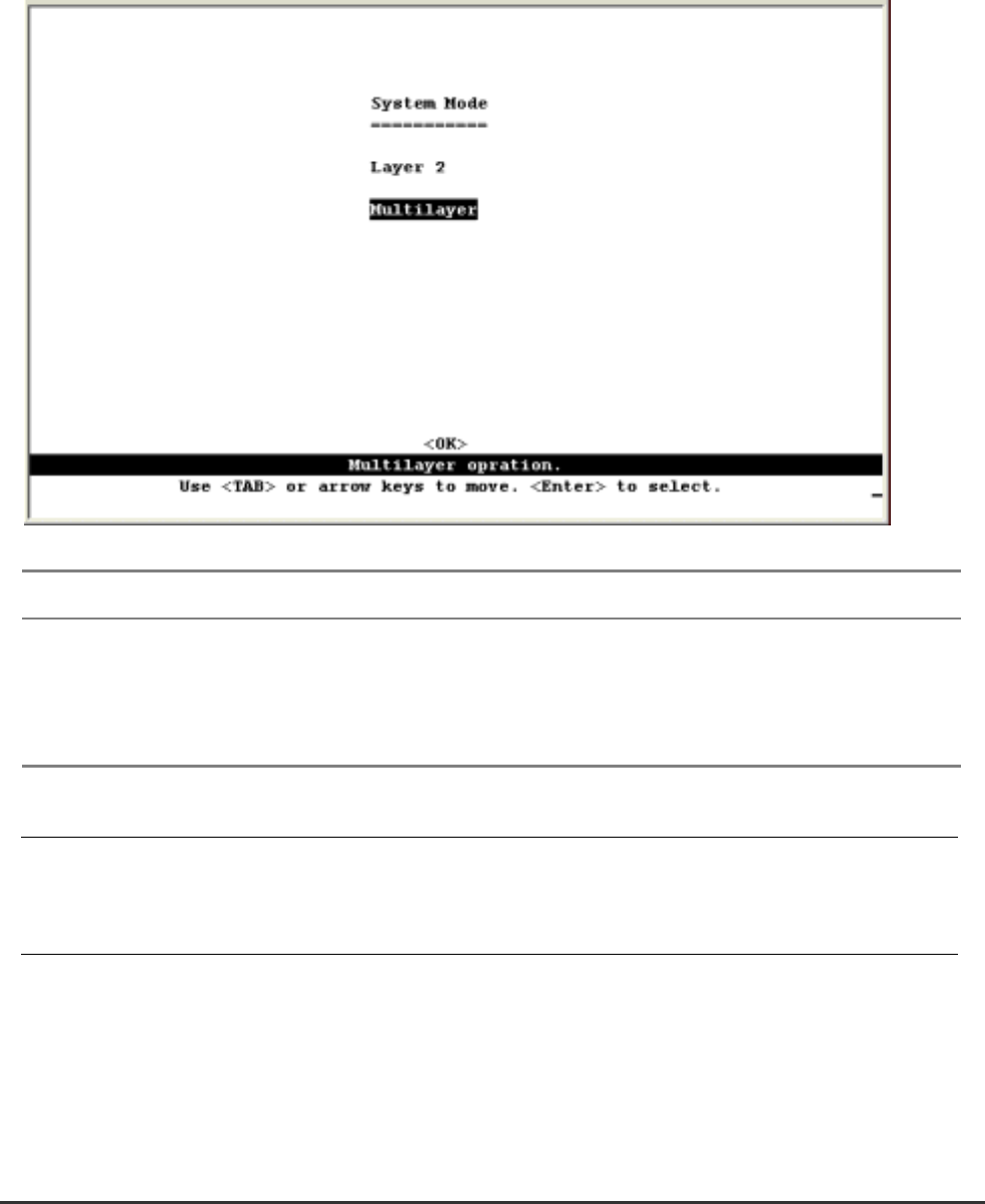
4.5.1 Setting the System Operation Mode
WGS3-2620 can be set to operate as a Layer 2 switch, making all filtering and forwarding decisions
based strictly on MAC addresses. Or it can be set to operate as a multilayer routing switch, whereby it
switches packets for all non-IP protocols (such as NetBUEI, NetWare or AppleTalk) based on MAC
addresses, and routes all IP packets based on the specified routing protocol. The System Mode menu is
shown below. Note that the switch will be automatically rebooted whenever the system operation mode is
changed.
Parameter Description
Layer 2 Filtering and forwarding decision will be based on MAC addresses for all protocol
traffic.
Multilayer Switching based on MAC addresses will be used for all non-IP protocol traffic, and
routing will be used for all IP protocol traffic.
NOTE: When the switch is set to multilayer mode, the IP menus are enabled, and the “IP Configuration
(Layer 2 Mode)” menu is disabled. When operating in multilayer mode, you should configure an
IP interface for each VLAN that needs to communicate with any device outside of the VLAN.
(See “Subnet Configuration”)