
Gigabit Ethernet Switch User's Manual
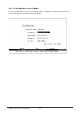
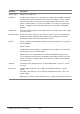
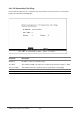
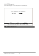
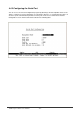
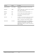
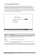
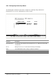
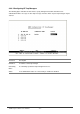
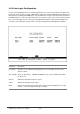
Table Of Contents
- Chapter 1. Introduction
- Chapter 2. Installing the Switch
- Chapter 3. Switch Management
- Chapter 4. Console Interface
- 4.1 Login Screen
- 4.2 Main Menu
- 4.3 System Information Menu
- 4.4 Management Setup Menu
- 4.5 Device Control Menu
- 4.5.1 Setting the System Operation Mode
- 4.5.2 Layer 2 Menu
- 4.5.3 Using the Bridge Menu
- 4.5.4 Configuring Virtual LANs
- 4.5.5 Configuring IGMP Snooping
- 4.5.6 Configuring IP Settings
- 4.5.7 Security Menu
- 4.5.8 Jumbo Packet Configuration
- 4.6 Monitoring the Switch
- 4.6.1 Displaying Port Statistics
- 4.6.2 Layer 2 Address Tables
- 4.6.3 Displaying Bridge Information
- 4.6.4 Displaying VLAN Information
- 4.6.5 IP Multicast Registration Table
- 4.6.6 IP Address Table
- 4.7 Resetting the System
- 4.8 Logging Off the System
- Chapter 5. Web Interface
- 5.1 Web-Based Configuration and Monitoring
- 5.2 Navigating the Web Browser Interface
- 5.3 Panel Display
- 5.4 Main Menu
- 5.5 System Information Menu
- 5.6 Management Setup Menu
- 5.7 Device Control Menu
- 5.7.1 Layer 2 Menu
- 5.7.2 Using the Bridge Menu
- 5.7.3 Configuring Virtual LANs
- 5.7.4 Configuring IGMP Snooping
- 5.7.5 Configuring IP Settings
- 5.7.6 Configuring Security Filters
- 5.7.7 Jumbo Packet Configuration
- 5.8 Monitoring the Switch
- 5.9 Resetting the System
- Chapter 6.Advanced Topics
- Appendix A Troubleshooting
- Appendix B Pin Assignments
- GLOSSARY

WGS3 Layer 3 Switch User’s Manual
- 24 -
Parameter Description
Interface Type Indicates IP over Ethernet.
IP Address IP address of the switch you are managing. The system supports SNMP over UDP/IP
transport protocol. In this environment, all systems on the Internet, such as network
interconnection devices and any PC accessing the agent module must have an IP
address. Valid IP addresses consist of four numbers, of 0 to 255, and separated by
periods. Anything outside of this format will not be accepted by the configuration
program.
Subnet Mask Subnet mask of the switch. This mask identifies the host address bits used for routing
to specific subnets.
Default Gateway Gateway used to pass trap messages from the system’ s agent to the management
station. Note that the gateway must be defined (when operating at Layer 2) if the
management station is located in a different IP segment.
IP State Specifies whether IP functionality is enabled via manual configuration, or set by Boot
Protocol (BOOTP).
Options include:
USER-CONFIG - IP functionality is enabled based on the default or user specified IP
Configuration. (This is the default setting.)
BOOTP Get IP - IP is enabled but will not function until a BOOTP reply has been
received. BOOTP requests will be periodically broadcasted by the switch in an effort
to learn its IP address. (BOOTP values can include the IP address, default gateway,
and subnet mask.)
VLAN ID The VLAN used for management access when “Mgmt VLAN” is selected. See the
next item.
Mgt. Access Specifies which VLAN have access right to its management interface. Options
include:
All VLANs – All VLANs have access right to its management interface. (This is the
default setting.)
Mgmt VLAN – Only the specified VLAN have access right to its management interface